My idea for the Creative Switch
project is a little town enclosed inside a kitchen container dish with a
lid. I have called it LED LAND.
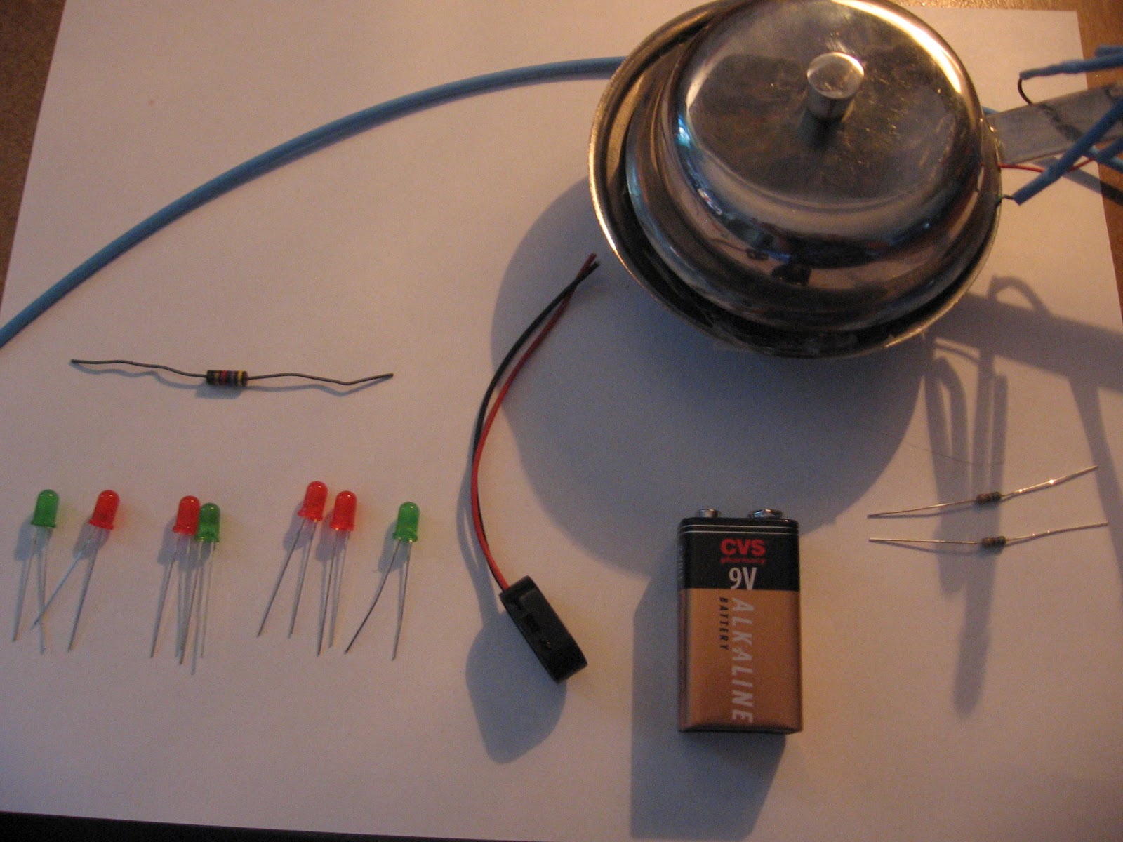
Materials
- kitchen container dish
- one diode
- two 560
ohm resistors - 47 ohm
resistor - relay
- 7 total
LEDs - 9 volt
battery - battery
clip - various
wires - insulating wire
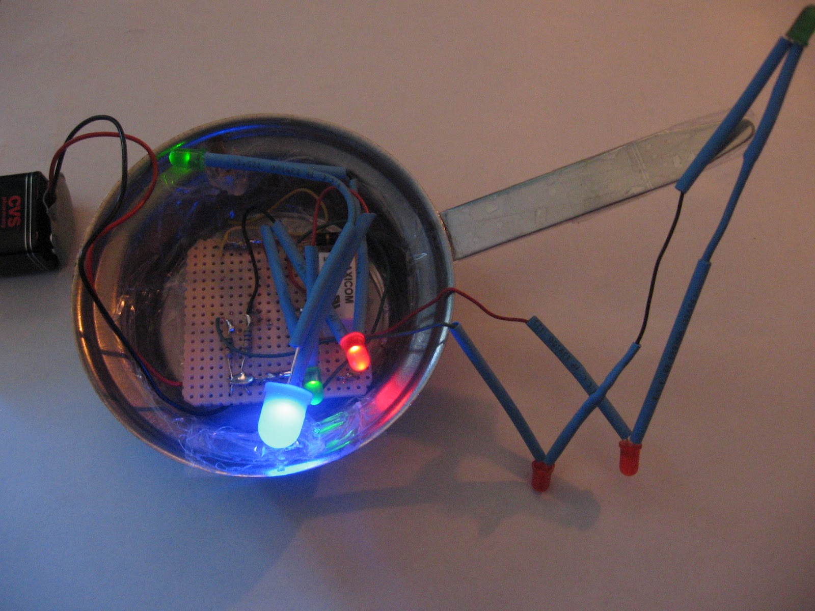
There are 3 LEDs on the handle of
the dish and 4 LEDs inside. When the lid is placed on top of the dish, the LEDs
on the handle will light up. The same thing will happen only when the lid is
off, the lights inside will go on, and the lights on the handle will go off.
the dish and 4 LEDs inside. When the lid is placed on top of the dish, the LEDs
on the handle will light up. The same thing will happen only when the lid is
off, the lights inside will go on, and the lights on the handle will go off.
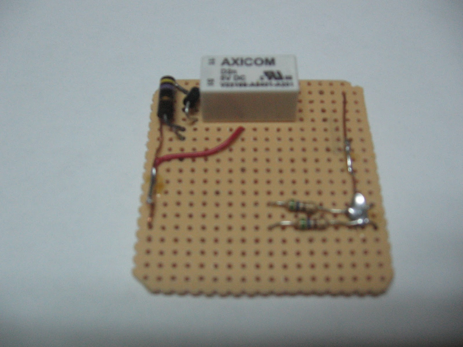
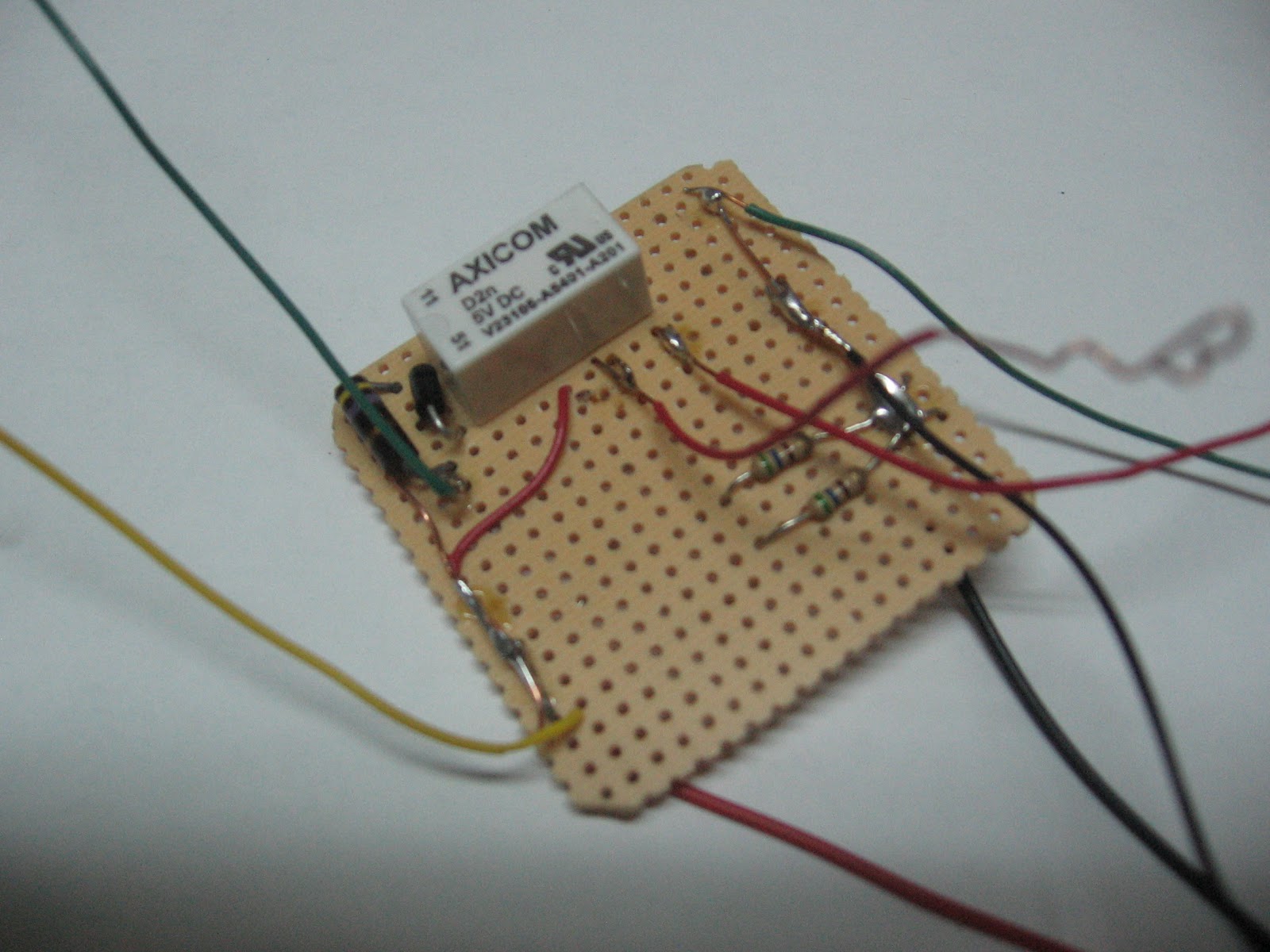
First, I constructed a breadboard
to place inside the container. I placed on there the relay, the two 560 ohm
resistors, the diode, and the 47 ohm resistor. In the first picture, I have
those things on the breadboard.
to place inside the container. I placed on there the relay, the two 560 ohm
resistors, the diode, and the 47 ohm resistor. In the first picture, I have
those things on the breadboard.
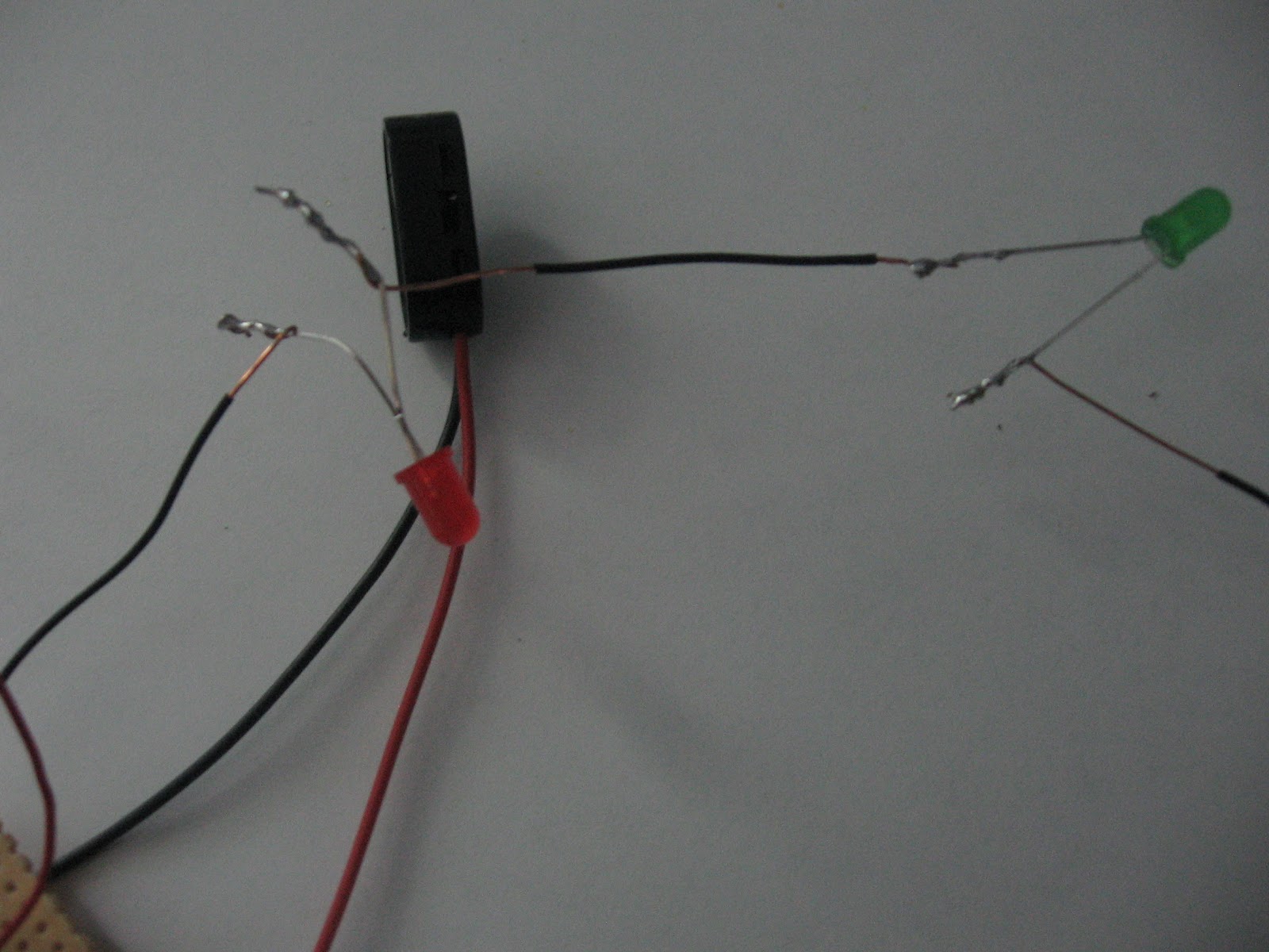
The relay is soldered to the outside wires as
well as the inside wires for the LEDs. In this particular photo, these are my soldering connections between the wires and LEDs.
well as the inside wires for the LEDs. In this particular photo, these are my soldering connections between the wires and LEDs.
Those two LED wires, one for inside and the other for outside, are each connected
to the 560 ohm resistors. I have the resistors connected to the LEDs to cut
back on the current that is going through as well as not to drain out the
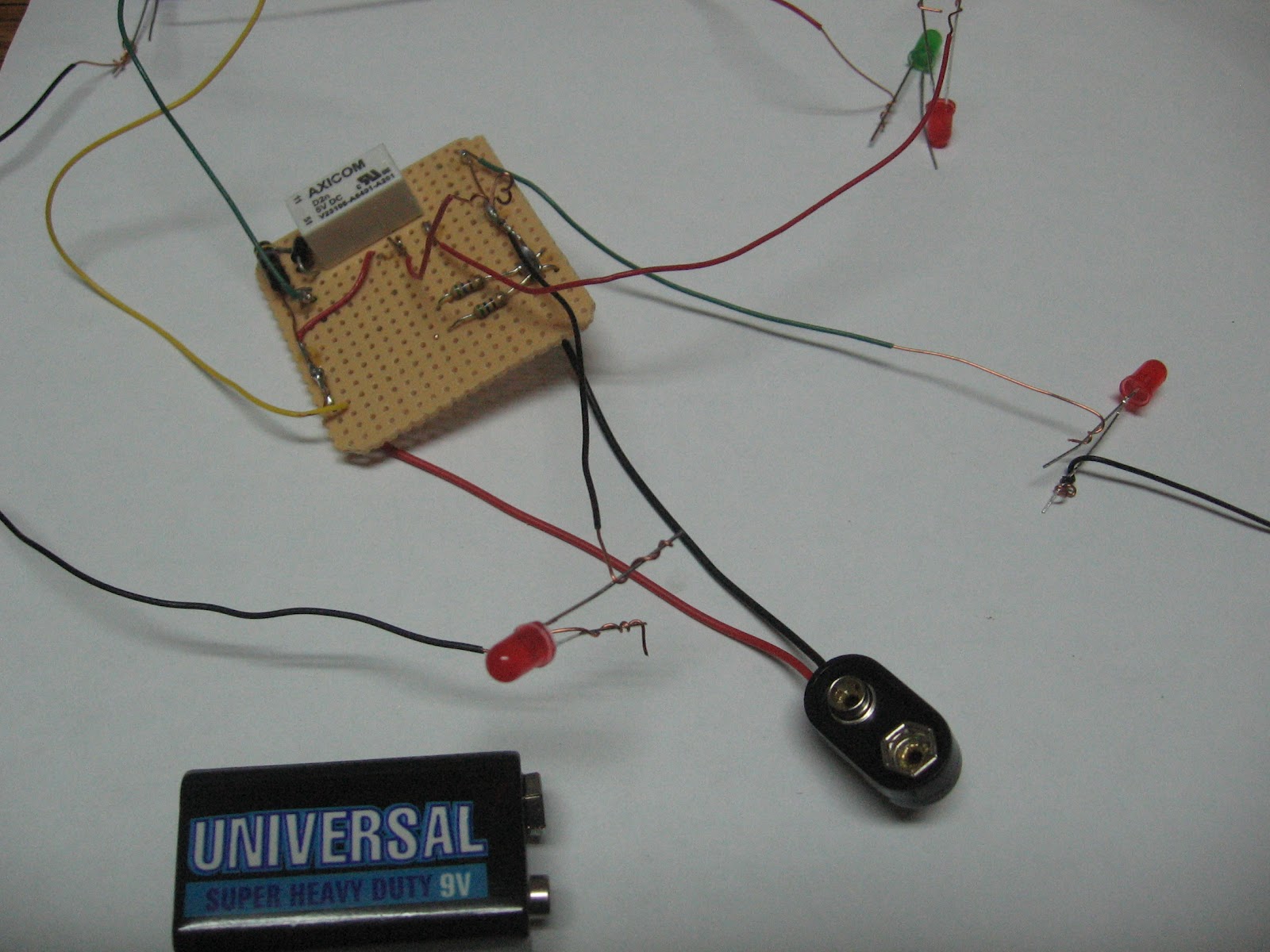
battery. On the 47 ohm resistor, I have two wires connected through the
breadboard. On the side of that resistor, it is the positive side. On the
opposite side is the negative side that is connected to the two 560 ohm
resistors. In the following picture, I have the basic setup of where everything
is placed along with the LED wires as well as the yellow and green wires which
are used for the copper plates in the closing and opening of the lid. The next picture shows a close-up of the setup
of the switch.
to the 560 ohm resistors. I have the resistors connected to the LEDs to cut
back on the current that is going through as well as not to drain out the
battery. On the 47 ohm resistor, I have two wires connected through the
breadboard. On the side of that resistor, it is the positive side. On the
opposite side is the negative side that is connected to the two 560 ohm
resistors. In the following picture, I have the basic setup of where everything
is placed along with the LED wires as well as the yellow and green wires which
are used for the copper plates in the closing and opening of the lid. The next picture shows a close-up of the setup
of the switch.
In the next step, I cut through a
battery clip by exposing it to the wires. Those wires were then connected to
the positive and negative wiring on the breadboard. This is so when the battery
is placed on the clip, the lights will shine depending on the action. After
this, I have yellow and green wiring on the breadboard that connects to two
small copper plates on the inside of the container. This is used so whether the
lid is placed on or off the lights will follow the action. When the lid is on,
the lights on the outside will be on. When the lid is off, the lights inside
will be on.
When placing the switch inside the
metal container, I noticed a buzz while the switch was used with the battery. I
was advised to use insulation for the bottom of the container, the sides, and
the wires holding the LEDs because the metal was shorting out the circuit.
Before I was ready to put the switch inside permanently, I placed a plastic
piece from a container inside. Then I put tape on the sides of the container as
well as the handle as well as the wiring itself. In the next picture, I have a
rough layout of the LED wires with insulation inside the container.
In the switch circuit, I have
approximately 9 volts. Four volts is what I have for the 47 ohm resistor which
is on one side of the relay. On the other side I have the remaining 5 volts at
approximately 60 ohms. Altogether this puts out 80 mA. Initially for this creative switch, I had intended to use a photo resistor for the inside LEDs, however I used a relay to direct the current of which lights will be on and off while the circuit is in function. My dad gave me some assistance in this project, or if something in the switch did not work properly. For instance, when I tested out the lid, one of my LEDs blew out as well as I connected the wiring wrong on the breadboard. I was not getting a voltage reading out of that particular LED. As a result when I placed the lid on top of the container, the outside LEDS did not turn on at all. I had mixed up what was going into ground, and that is why all 3 LEDs did not light up including the blown out LED.
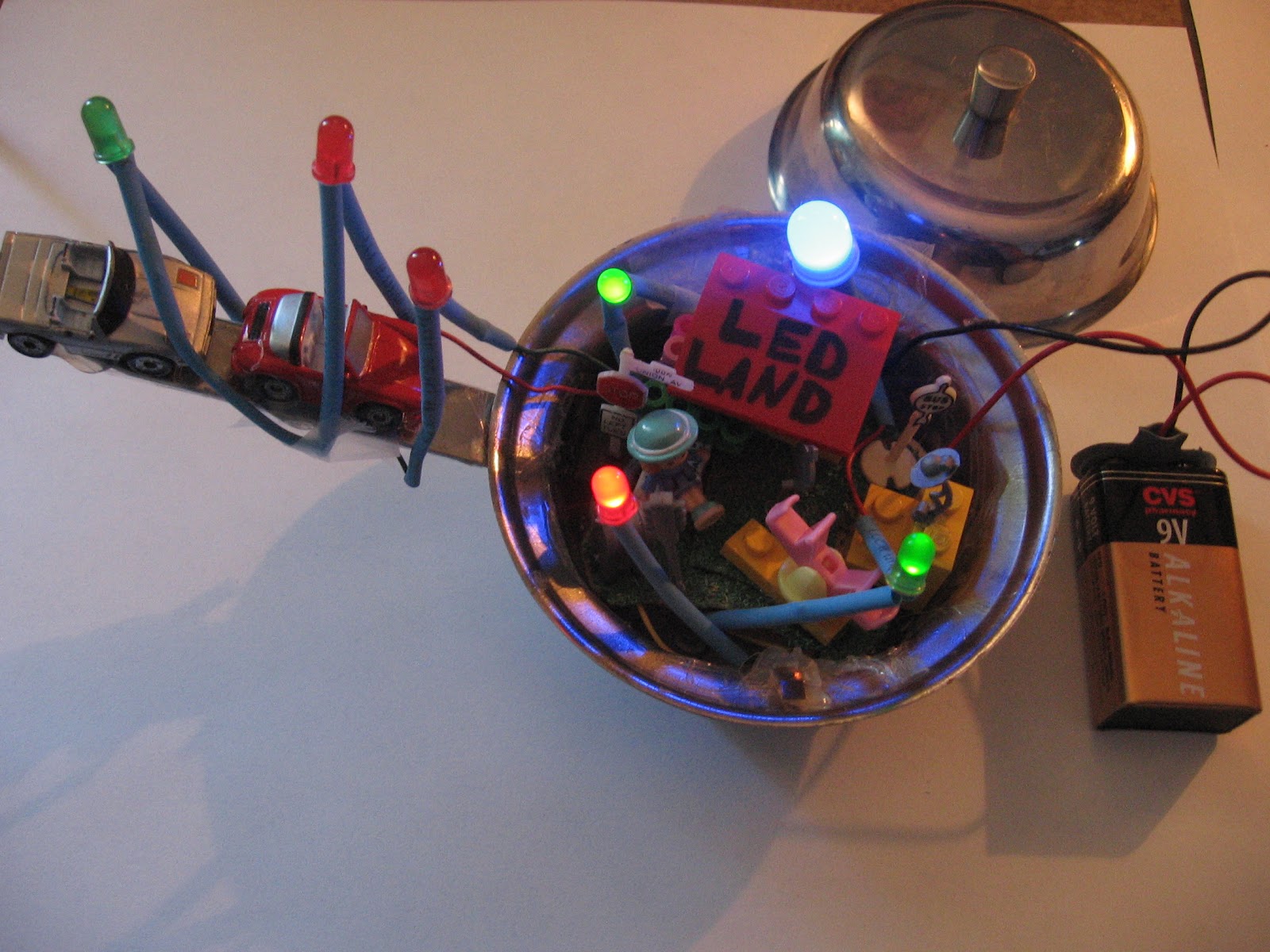
As for the creative side of my
piece, I loved the idea of having a little town inside even though I was
working with very limited space inside the container. I also developed more
ideas along the way. All of the items I found in my house such as the legos or various things from a model train set. I had found these little toy cars to place on the handle
going in the direction of LED Land. This was a later idea because the way
I have the LEDS standing up on the handle it creates a bridge looking as if the
cars are on a bridge. The town has various things such as legos for buildings,
a mailbox, a signpost, LED lights, and of course, Polly Pocket. Also, with the
limited space inside the container, I have the battery placed outside. The
battery has legos on it in which it has become ComEd that supplies power and
light to the town. Explore LED LAND. There’s so much to see!
This is LED LAND with the lid off.
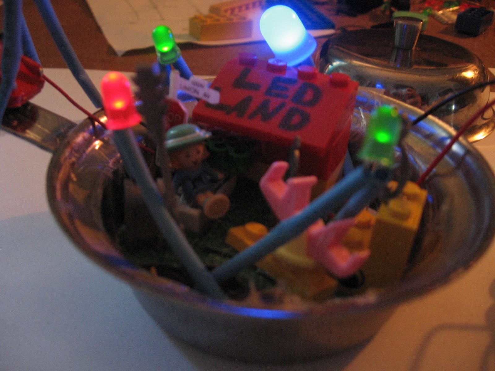
This is a close up look of LED LAND.
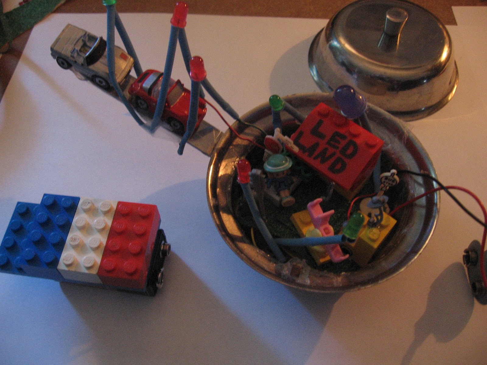
This is the whole view of LED LAND.
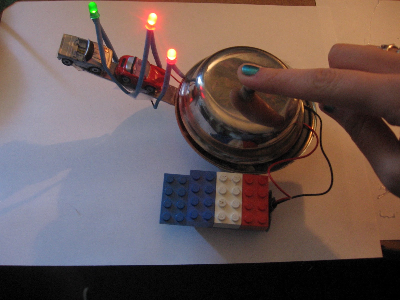
This is LED LAND with the lid on, and the ComEd electricity (battery).
~Angela Zarek
Responsive Arts