Ashley Villagrana
Teacher: Sabrina Raaf.
General Materials Needed(for 3 projects shown)
1. Soldering Iron
2. Rosin
3. Heat shrinks
4. Wire Stripper
5. Wire Cutter
5. LED(preferably red ones)
6. sponge
7. Little red cups
8.Alligator Clips
9. 9V battery
10. Tape.
11. Cardboard.
12. Construction Paper
13. Markers
14. Little Container
15. 150 Ohm resistor
16. Toggle Switch
17. Good wooden frame(For Keyboard circuit)
Piano Ruler,
Have you ever wanted to get out a musical jam in a classroom while your teacher is away the piano ruler will be able to provide that. The only problem was a Piano on a ruler would be hard to conceal or would it. By looking at previous rulers I was able to find the perfect design.
This ruler is where I am inspired by it is a hole puncher ruler
It is a ruler with a secret compartment for a piano. So it was a perfect diagram for the Piano Ruler.
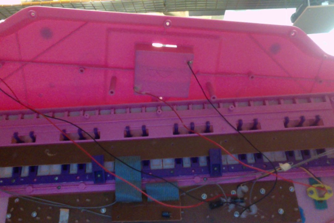
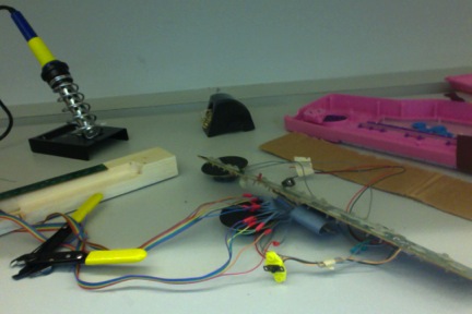
was needed was a cheap piano keyboard which was obtained at the flea market. This was perfect, lots of keys and even had the function to change in instrument and beat. It was easy to open and then was able to find two components a circuit for the keyboard, and a circuit for the sound system.
Open and ready to hack. You could clearly see the two circuit boards of brown.
Problems arose as to where to put it, the wires to the actual keyboard circuit was a tad short and it would seem weird and hard to conceal the other board that was with it. So the solution was to make it longer.
How?
What was to be done was long and tedious. I had to match the small chip while making the wires longer to the music library after I desoldered the wires from the keyboard circuit.
Step 1: First to do was desolder the rosin off keyboard circuit and unhook old wires.
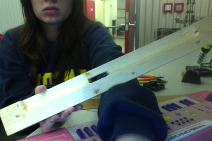
Step 2: Going to Wood shop: make dimensions that fit the circuit. Make a indent in the wood to fit the chip. Then measure where the hole would be from the indent to the back. This depends entirely
where your wires are placed on the circuit. Purpose of that is so you can lead the wires through the back of the ruler so it’d be easier to hide from plain site.
Step 3: As said previously when you got your ruler wood frame lead the wires through the hole then I was able to start soldering.
Step 4: Grab some new wires and strip and solder the wires make sure you get the same amount of wires as to how many wires are still on the music library.
Step 5: MAKE sure the heat shrinks are on each wire before you continue. Reason is so you don’t
short circuit the board.
Step 6: Then after that is completed solder the new freshly soldered wires that you’ve just done to the music library. (NOTE:Most important make sure they match as they had labels that need to match.)
Step 7: Now bring up each heat shrink to each newly soldered area you did in Step Four. Then
using the soldering iron to heat it slowly so that it can tighten.
What I was going to do.
Step 8: Hiding the soundboard: Was going to hide the soundboard within the binder.
Step 9: Then using copper on finger tips would allow the user ONLY to play onto the board so if the
someone else were try to play it, the item would not be playing.
So What I did some of the process with Pics
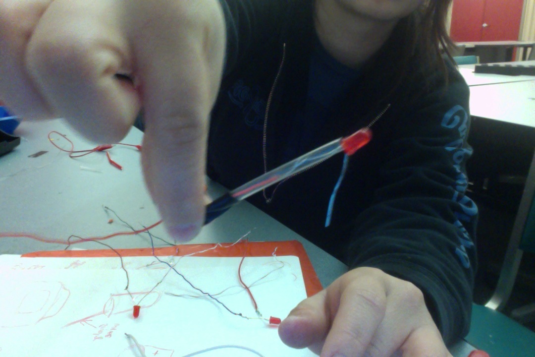
Cutting some wires.
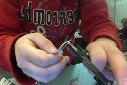
Stripping the tips the tips before soldering them to the new wires.
Heating the heat-shrinks on the soldered part of the new wire so that the wires don’t touch and short circuit out.
This is what it looks like to hook the new extended wires to the old ones.
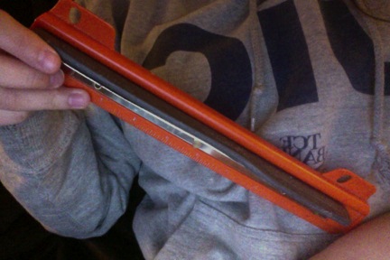
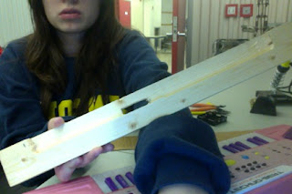 Outlook of the ruler frame. After measuring
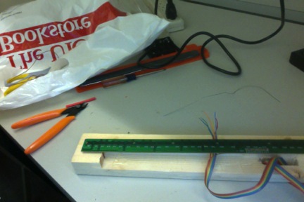
.

With the help of Ben we were able to test the circulation through the whole circuit.
Conclusion:
Good news what I did with the soldering and connecting of the wires did not kill the keyboard as the battery was letting out voltage all the way to the keyboard circuit; however the circuit did not start. There was a dead set of resistors on the sound mixer board. Sadly there was no going further as it became to complicated and hard to even try to fix after that. The reasons I formulated that caused the problem.
1. It was raining Friday(but I tried to cover the project even though it kinda protruded out of the bag)
2. Walking all day.(Even flights of stairs and hitting into things)
3. I probably killed it by connecting it to a wall wart.
The Next Project the Origami Flower light.
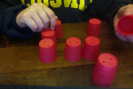
Trying to conduct a simpler circuit at home and looking through the house I found some interesting buckets with holes in them.
The thought of maybe I can connect them to this small flower.
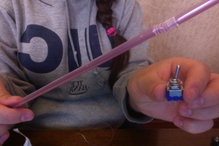
with what I had I wanted to make a lighted origami flower attached to a toggle switch.

Found some straws figured it could be the stem of the flower and a good support and separator of the power and resister of the LED light.
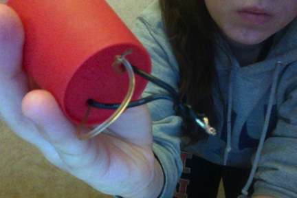
on outside and power inside I would try to make the wires go out through the bottom on the small bucket
and Ground come out the back end.
Steps:
1: Solder your 150 ohms resistor to your red LED.
2: Then cut some straws to how big you would want the stem of the flower to be.
3: Measure the wire and lead the power wire through the straw and tie it down with tape.
4: Found out that you could make two by doing process one to three again and connecting both of
Grounds to the Neg of the 9Volt Battery while the both power wires connect at one end of the
toggle switch and the other is tied to the Positive making it a parallel circuit.
5: Place origami flower(with hole on the bottom) atop the LED make sure the LED is visible when
you do.
6: Flick the switch and it should come on.
Conclusion:
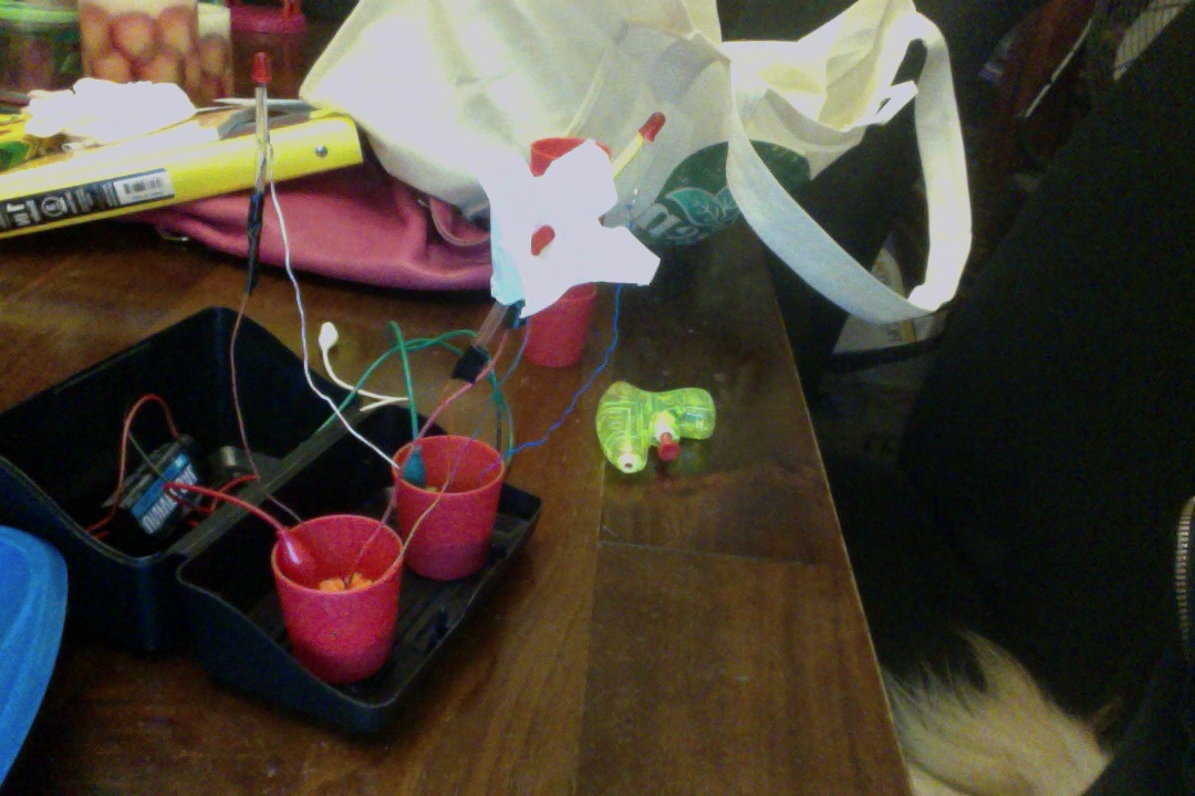
I did kill three LED’s unfortunately because I believe the wire was too thick and caused less resistance of the flow of voltage through the wires. I was stuck using one LED as to trying to make a parallel circuitt and adding another flower. I barely able to manage to keep one LED lit and connected to a toggle switch. The battery was inserted inside bucket and excess wires taped to outside of bucket.
Hopefully I’ll get to add more soon.
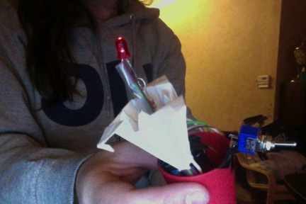
you get a interesting small origami lamp light for your room for your enjoyment. Lighted up and ready for action.
P.S Someone told me with this toggle you could have it stick out of a surface so you can have it secured and more easier than this pic to turn on and off.
Finale! Another twist to the project Origami little Lamp structure.
There was the same setup with the LED however with the inclusion of wet sponges. Remember how I mentioned the LED in a straw well instead did it with a heat shrink on one side and no resister as the sponges provided resistance to the wires.
So two wires to a LED was enough to light the circuit. I made three of these exactly the same.(PS. we did try adding a resistor but it made the lights to dim so testing it out it turned out to be okay with just the two wires and LED.
Using two small buckets but two cut circular wet sponges(one sponge would have to be ground “neg” and one “pos”) with and make sure to stab the wires through the sponge so it won’t be too lose and fall out.(The wires to make it stand had to be very sturdy wires and so the previous wires was replaced.)
Well there is always a problem as the buckets has holes on the bottom so if they wet eachother a short circuit is bound to happen. So what I did was to find a small plastic container to hold one while the other is laying within the stand(It is a index card holder container)
The other issue was trying to find a way to hide the wires. So looking I found some cardboard and decorated the stand to try to camouflage the wires and batteries. Was trying really hard to poke the power and negative power from the 9V battery into the backsides of the box as a concealing method but much to my avail it kept shifting out and we needed a better way to turn on these plants.
So using alligator clips would be really simple to hook to the sponge but another problem arose. What to do with all the extra wires and clips? Back part of the stand was the best way to go about it. Getting some cardboard and decorating a background for the flowers gave it a hidden touch. The process of taping and holding things done was what it was given and then.
Steps.
1. Get 3 red LED’s
2. Strip the ends and solder the tips.
3. Solder those tips to the LED’S, one for each end.(So in the end you should have three LED’S like
this.
4. Use a heat shrink on one side of the LED’s so they don’t burn out each other.
5. Grab two sponges and get your two little buckets.
6. Cut the sponges to fit within the little buckets.
7. Stab the sturdy wires to their respective sponges Positive wire to Positive sponge(or what you have
chosen) and Negative wire to Negative sponge.(They are going to be going across the mini buckets)
8. Grab your 9V and you the positive and negative wire topper to easily get access to the power.
9. Remember to have the wires to the battery soldered.
10. Connect two alligator clips to the two wires and start placing them in the top part of the container.
11. Find a tiny container for one bucket and place the bucket in there. (Secure it with tape if anything)
12. Place these containers in the index container and secure it down(I did so with tape)
13. To cover the top was I made a cardboard decorative flap to cover the wires. But have the tip ends of
the alligator clips out in front.
14. To make a sturdy holding place a cardboard piece.(cover it up with colored paper) and tape the
structure on it.
15. Get some water put it on the sponges and lead the alligator clips(positive to positive to positive
sponge. Negative to Negative sponge) and your 3 Led’s should light up.
16. Get your three origami paper flowers and cut a hole at the bottom.
17. Place them atop each LED you can fasten them down with tape so they don’t fall off.

A Origami Flower Stand was created,
The lights are lit in this pic.