project proposal, I would like to continue off my first creative switch project
of the LED land which I am very passionate about. I want this advanced on a
much bigger scale physically as well as its functionality. So far I have these
figurines of the Eiffel Tower, the Leaning Tower of Piza, the Statue of
Liberty, the pyramid of Cholula, Big Ben, and a small airplane. With that, I
want this to represent an international world, but at the same time I want it
to be modern and futuristic with the use of LEDs as well as the artistic
expression in this world. By this I want it to show the international world at
a very futuristic level with bold and colorful sculptures and colorful
sidewalks and roads. I also have these fiber optic wands that light up with a
switch button. I would like to incorporate those as glistening stars when the
lid is on. I definitely would like to capture them twinkling in and out.
this land area, I have a large vegetable dip tray that has its own dividers,
which could be used to separate the different areas of the world. I also would
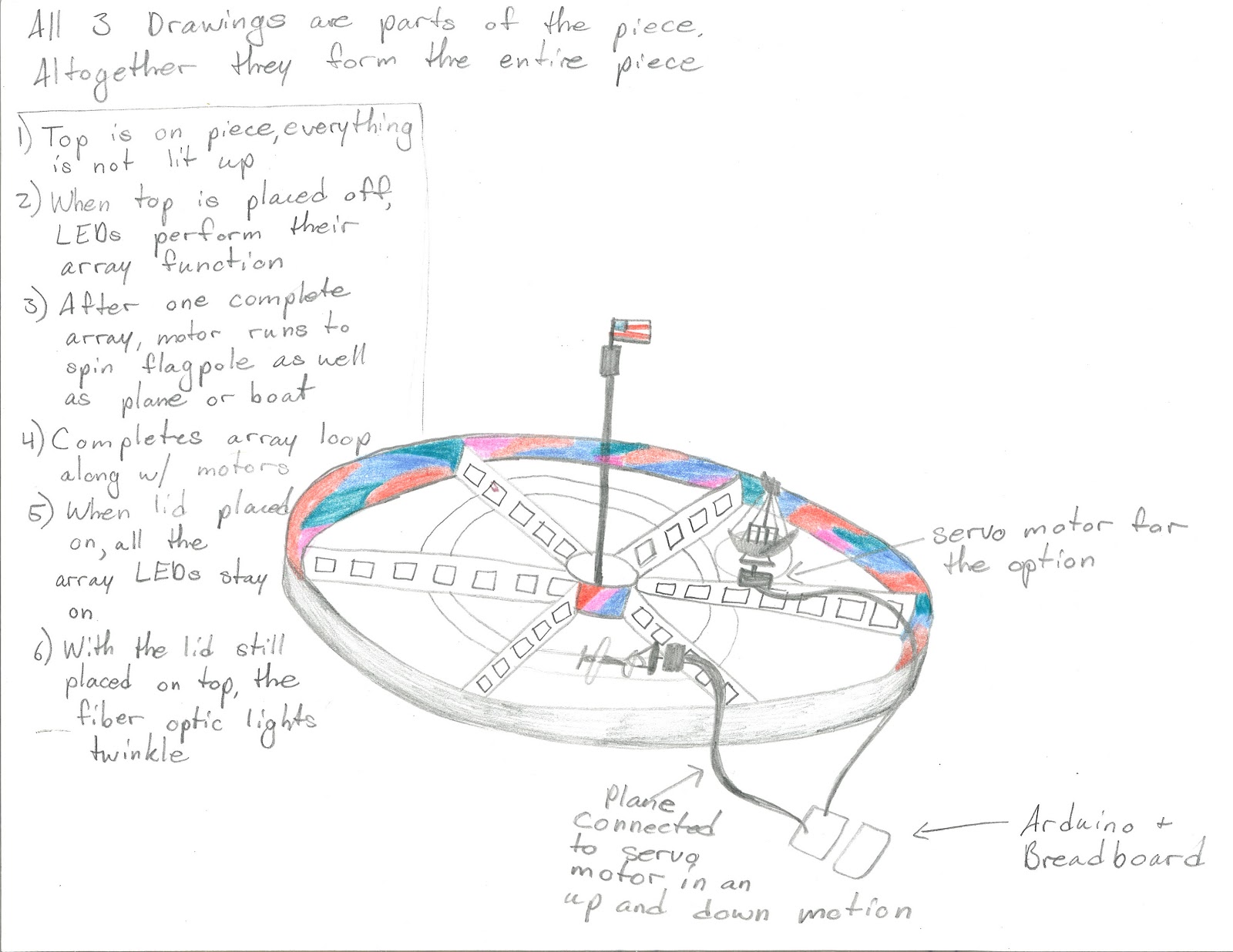
like to have a clear dome to place on top and have that relay switch as
continued from the first project. This would be different so that when the top
is on it would symbolize night time and the fiber optic wands would perform
their function of dimming in and out. When the top is off, the regular green
and red LEDs on the dividers would perform an array function from one light to
the next.
also would like to have an American flag run by a DC motor in a fairly slow
movement to show the movement on a flagpole in the wind. With my small airplane
or a miniature boat, I would like to incorporate either a takeoff or movement in
the air for the airplane or the sailing of the boat in the waves. This leads to
my questions. How could I best show a movement of the airplane with a DC motor
or servo motor? If I also wanted to have
lit up sidewalks that perform in an array, what could I use to best show that
they are sidewalks despite the shape of the LEDs? For the fiber optic wands,
what is the best possible way to connect them to a relay switch?


This is the updated code for 3 shift registers for the aqua blue LEDS
/* ———————————————————
* | Arduino Experimentation Kit Example Code |
* | CIRC-05 .: 8 More LEDs :. (74HC595 Shift Register) |
* ———————————————————
* ARRAY AND SHIFT REGISTER CODE!!!! with aquablue lights
* shift registers for 8 leds for register 1
*8 leds for register 2
*8 leds for register 3
* We have already controlled 8 LEDs however this does it in a slightly
* different manner. Rather than using 8 pins we will use just three
* and an additional chip.
*
*
*/
//Pin Definitions
//Pin Definitions
//The 74HC595 uses a serial communication
//link which has three pins
//shift register 1
int data = 2;
int clock = 3;
int latch = 4;
// shift register 2
int data2 = 2;
int clock2 = 3;
int latch2 = 4;
//shift register 3
int data3 = 2;
int clock3 = 3;
int latch3 = 3;
//Used for single LED manipulation
int ledState = 0;
const int ON = HIGH;
const int OFF = LOW;
int i;
/*
* setup() – this function runs once when you turn your Arduino on
* We set the three control pins to outputs
*/
void setup()
{
pinMode(data, OUTPUT);
pinMode(clock, OUTPUT);
pinMode(latch, OUTPUT);
// shift register 2
pinMode (data2, OUTPUT);
pinMode (clock2, OUTPUT);
pinMode (latch2, OUTPUT);
//shift register 3
pinMode (data3, OUTPUT);
pinMode (clock3, OUTPUT);
pinMode (latch3, OUTPUT);
}
/*
* loop() – this function will start after setup finishes and then repeat
* we set which LEDs we want on then call a routine which sends the states to the 74HC595
*/
void loop() // run over and over again
{
int delayTime = 50; //the number of milliseconds to delay between LED updates
for(int i = 0; i < 8; i ++)
{
changeLED(i, ON);
delay(delayTime);
}
for(int i = 0; i < 8; i ++)
{
changeLED(i, OFF);
delay(delayTime);
}
//for(int i = 0; i < 256; i++){
// updateLEDsLong(i);
// updateLEDs(i);
delay(delayTime);
// }
}
/*
* updateLEDs() – sends the LED states set in ledStates to the 74HC595
* sequence
*/
void updateLEDs(int value)
{
digitalWrite(latch, LOW); //Pulls the chips latch low
shiftOut(data, clock, MSBFIRST, value); //Shifts out the 8 bits to the shift register
digitalWrite(latch, HIGH); //Pulls the latch high displaying the data
//
//
digitalWrite(latch2, LOW); //Pulls the chips latch low
shiftOut(data2, clock2, MSBFIRST, value); //Shifts out the 8 bits to the shift register
digitalWrite(latch2, HIGH); //Pulls the latch high displaying the data
//
//
digitalWrite(latch3, LOW); //Pulls the chips latch low
shiftOut(data3, clock3, MSBFIRST, value); //Shifts out the 8 bits to the shift register
digitalWrite(latch3, HIGH); //Pulls the latch high displaying the data
}
/*
* updateLEDsLong() – sends the LED states set in ledStates to the 74HC595
* sequence. Same as updateLEDs except the shifting out is done in software
* so you can see what is happening.
*/
void updateLEDsLong(int value){
digitalWrite(latch, LOW); //Pulls the chips latch low
for(int i = 0; i < 8; i++){ //Will repeat 8 times (once for each bit)
int bit = value & B10000000; //We use a “bitmask” to select only the eighth
//bit in our number (the one we are addressing this time through
value = value << 1; //we move our number up one bit value so next time bit 7 will be
//bit 8 and we will do our math on it
if(bit == 128){digitalWrite(data, HIGH);} //if bit 8 is set then set our data pin high
else{digitalWrite(data, LOW);} //if bit 8 is unset then set the data pin low
digitalWrite(clock, HIGH); //the next three lines pulse the clock pin
delay(1);
digitalWrite(clock, LOW);
}
digitalWrite(latch, HIGH); //pulls the latch high shifting our data into being displayed
}
//These are used in the bitwise math that we use to change individual LEDs
//For more details http://en.wikipedia.org/wiki/Bitwise_operation
int bits[] = {B00000001, B00000010, B00000100, B00001000, B00010000, B00100000, B01000000, B10000000};
int masks[] = {B11111110, B11111101, B11111011, B11110111, B11101111, B11011111, B10111111, B01111111};
/*
* changeLED(int led, int state) – changes an individual LED
* LEDs are 0 to 7 and state is either 0 – OFF or 1 – ON
*/
void changeLED(int led, int state){
ledState = ledState & masks[led]; //clears ledState of the bit we are addressing
if(state == ON){ledState = ledState | bits[led];} //if the bit is on we will add it to ledState
updateLEDs(ledState); //send the new LED state to the shift register
}
Recent Code
/* ———————————————————
* | Arduino Experimentation Kit Example Code |
* | CIRC-05 .: 8 More LEDs :. (74HC595 Shift Register) |
* ———————————————————
* ARRAY AND SHIFT REGISTER CODE!!!! with 2 FIBER OPTIC LIGHTS
AND MOTOR
* 1 shift register for fiber optic lights, motor, and music
* We have already controlled 8 LEDs however this does it in a slightly
* different manner. Rather than using 8 pins we will use just three
* and an additional chip.
*
*
*/
int buttonState;
int ledPin2 = 11; //
//Pin Definitions
//Pin Definitions
//The 74HC595 uses a serial communication
//link which has three pins
//shift register 1
int data = 2;
int clock = 3;
int latch = 4;
// shift register 2
int data2 = 5;
int clock2 = 6;
int latch2 = 7;
//shift register 3
int data3 = 8;
int clock3 = 9;
int latch3 = 10;
//shift register 4
int data4 = 11;
int clock4 = 12;
int latch4 = 13;
int ledPin = 4; //
const int buttonPin = 13;
//void cityON();
//Used for single LED manipulation
int ledState = 0;
const int ON = HIGH;
const int OFF = LOW;
int i;
/*
* setup() – this function runs once when you turn your Arduino on
* We set the three control pins to outputs
*/
void setup()
{
pinMode(data, OUTPUT);
pinMode(clock, OUTPUT);
pinMode(latch, OUTPUT);
// shift register 2
pinMode (data2, OUTPUT);
pinMode (clock2, OUTPUT);
pinMode (latch2, OUTPUT);
//shift register 3
pinMode (data3, OUTPUT);
pinMode (clock3, OUTPUT);
pinMode (latch3, OUTPUT);
//shift register 3
pinMode (data4, OUTPUT);
pinMode (clock4, OUTPUT);
pinMode (latch4, OUTPUT);
pinMode(buttonPin, INPUT);
Serial.begin(9600);
}
/*
* loop() – this function will start after setup finishes and then repeat
* we set which LEDs we want on then call a routine which sends the states to the 74HC595
*/
void loop() {
analogWrite(ledPin2, 0);
buttonState = digitalRead(buttonPin);
Serial.println(buttonState);
// run over and over again
while (digitalRead(buttonPin) == HIGH) { //button pushed
analogWrite(ledPin2, 0);
cityON(); //lid off
}
for(int i = 0; i < 16; i ++)
{
changeLED(i, OFF);
//delay(50);
}
//for(int i = 0; i < 256; i++){
// updateLEDsLong(i);
// updateLEDs(i);
for(int fadeValue = 0 ; fadeValue <= 255; fadeValue +=5)
{
// sets the value (range from 0 to 255):
analogWrite(ledPin2, fadeValue);
// wait for 30 milliseconds to see the dimming effect
delay(10);
}
for(int fadeValue = 255 ; fadeValue >= 0; fadeValue -=5) {
// sets the value (range from 0 to 255):
analogWrite(ledPin2, fadeValue);
// wait for 30 milliseconds to see the dimming effect
delay(10);
}
}
void cityON() {
int delayTime = 50; //the number of milliseconds to delay between LED updates
for(int i = 0; i < 16; i ++)
{
changeLED(i, ON);
delay(delayTime);
}
for(int i = 0; i < 16; i ++)
{
changeLED(i, OFF);
delay(delayTime);
}
//for(int i = 0; i < 256; i++){
// updateLEDsLong(i);
// updateLEDs(i);
delay(delayTime);
}
///*
// * updateLEDs() – sends the LED states set in ledStates to the 74HC595
// * sequence
// */
void updateLEDs(int value)
{
digitalWrite(latch, LOW); //Pulls the chips latch low
shiftOut(data, clock, MSBFIRST, value); //Shifts out the 8 bits to the shift register
digitalWrite(latch, HIGH); //Pulls the latch high displaying the data
//
//
digitalWrite(latch2, LOW); //Pulls the chips latch low
shiftOut(data2, clock2, MSBFIRST, value); //Shifts out the 8 bits to the shift register
digitalWrite(latch2, HIGH); //Pulls the latch high displaying the data
//
//
digitalWrite(latch3, LOW); //Pulls the chips latch low
shiftOut(data3, clock3, MSBFIRST, value); //Shifts out the 8 bits to the shift register
digitalWrite(latch3, HIGH); //Pulls the latch high displaying the data
//
}
/*
* updateLEDsLong() – sends the LED states set in ledStates to the 74HC595
* sequence. Same as updateLEDs except the shifting out is done in software
* so you can see what is happening.
*/
void updateLEDsLong(int value){
digitalWrite(latch, LOW); //Pulls the chips latch low
for(int i = 0; i < 8; i++){ //Will repeat 8 times (once for each bit)
int bit = value & B10000000; //We use a “bitmask” to select only the eighth
//bit in our number (the one we are addressing this time through
value = value << 1; //we move our number up one bit value so next time bit 7 will be
//bit 8 and we will do our math on it
if(bit == 128){digitalWrite(data, HIGH);} //if bit 8 is set then set our data pin high
else{digitalWrite(data, LOW);} //if bit 8 is unset then set the data pin low
digitalWrite(clock, HIGH); //the next three lines pulse the clock pin
delay(1);
digitalWrite(clock, LOW);
}
digitalWrite(latch, HIGH); //pulls the latch high shifting our data into being displayed
}
//These are used in the bitwise math that we use to change individual LEDs
//For more details http://en.wikipedia.org/wiki/Bitwise_operation
int bits[] = {B00000001, B00000010, B00000100, B00001000, B00010000, B00100000, B01000000, B10000000};
int masks[] = {B11111110, B11111101, B11111011, B11110111, B11101111, B11011111, B10111111, B01111111};
/*
* changeLED(int led, int state) – changes an individual LED
* LEDs are 0 to 7 and state is either 0 – OFF or 1 – ON
*/
void changeLED(int led, int state){
ledState = ledState & masks[led]; //clears ledState of the bit we are addressing
if(state == ON){ledState = ledState | bits[led];} //if the bit is on we will add it to ledState
updateLEDs(ledState); //send the new LED state to the shift register
}
I think that, if the space allowed, you could use some sort of paper or felt (not sure if that's the safest idea, but considering we're usually working with low voltage it shouldn't be much of a problem) to outline the sidewalks and place the LEDs on the top or along sides.