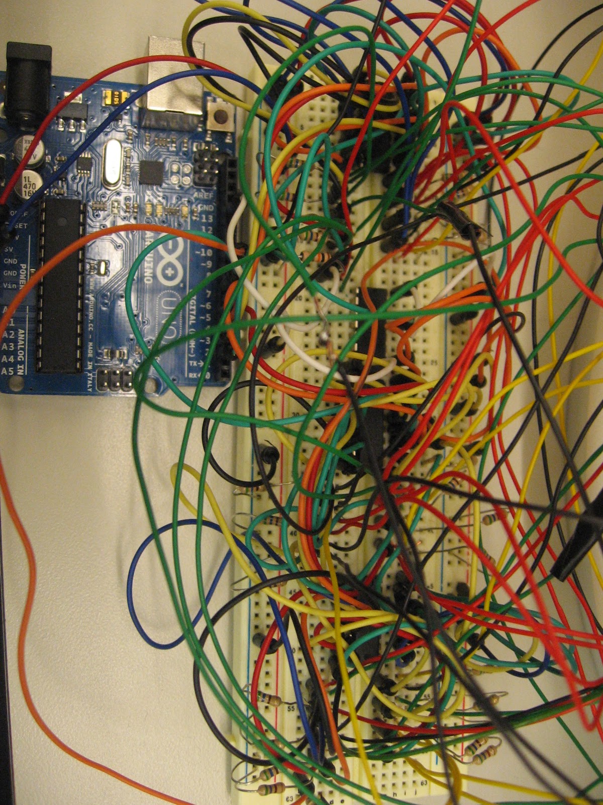
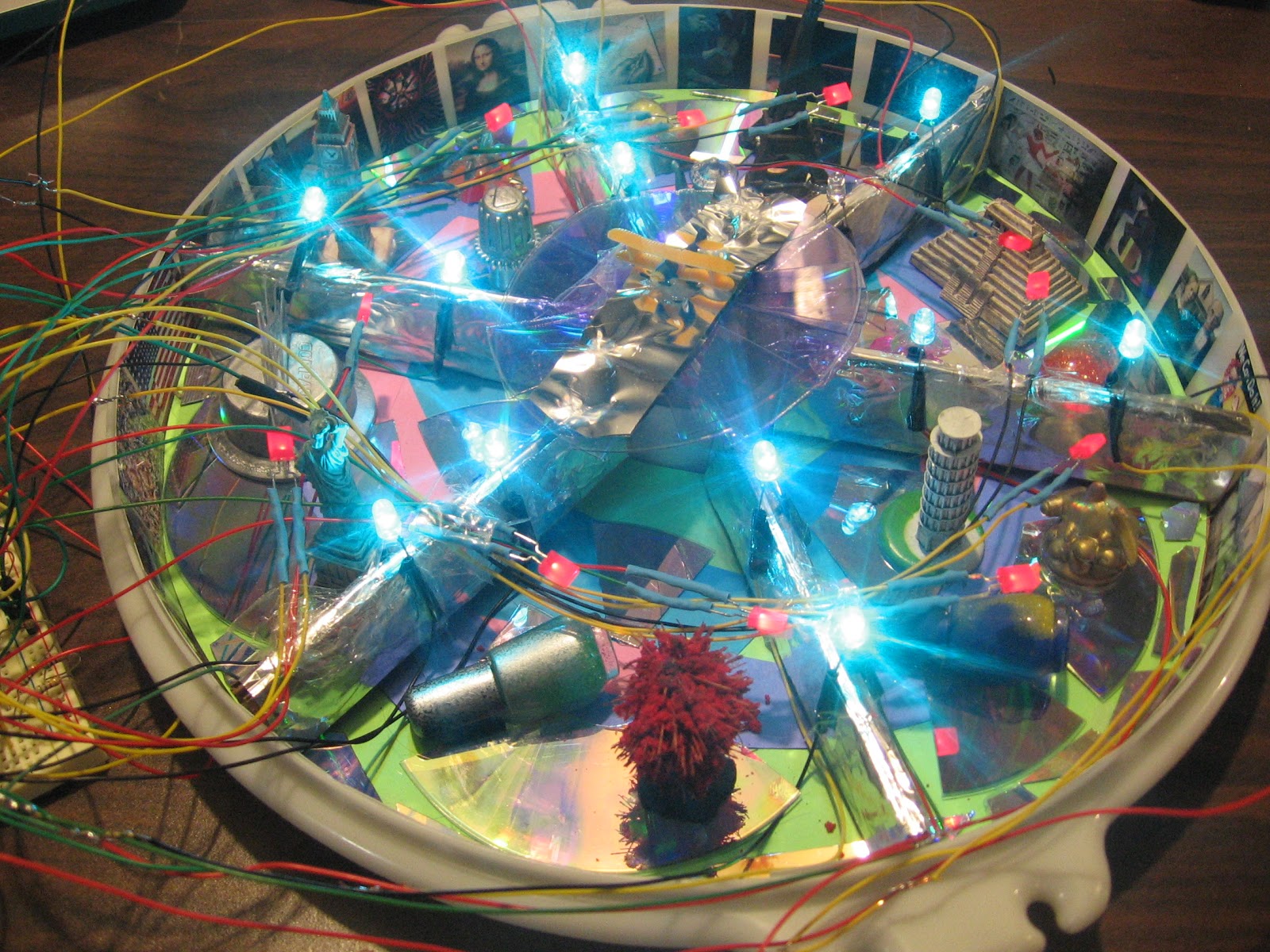
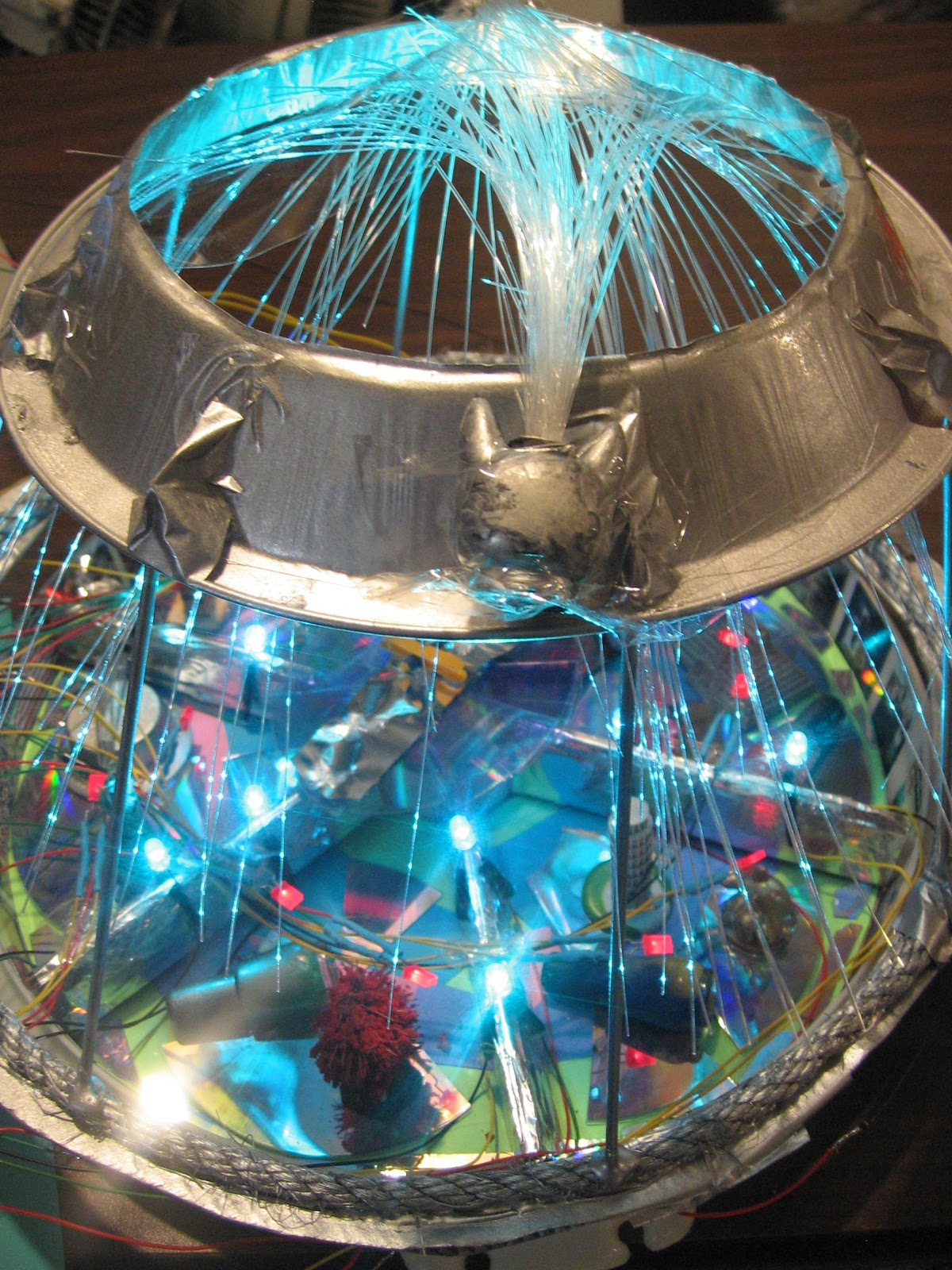
My project is an international futuristic art world both a representation of the art of the past, present, and future. I have figures of Big Ben, the Leaning Tower of Pisa, the Eiffel Tower, the Pyramid of Cholula, and the Statue of Liberty and various sculptures that I made for the piece. It is my interpretation and imagination of a futuristic art world that embraces artworks of the past and present and into the future. I ran into issues along the way in getting the array to work while getting the fade part of the LEDS to go on for the button mechanism. The LEDS for the fade would blink instead of fade for their part. I also had a mechanical issue in getting secure contact with the lid and the tray, so after rewiring to power and ground I was able to have the connection function properly. In this way, I can not entirely take the lid off of the tray since the wires are connected on the breadboard. This is the just one of things I would change in having more copper tape so it can have that immediate connection and be much easier to handle. I also would change the wiring of all the leds because it is a lot of wire to work with. I did try to eliminate as much as I could as I did have a lot of wires before. I know originally I wanted to have a motor and a song for when the dome goes off, but I was really focusing on getting the array and fade to work. I would have at least liked to put in the flag to have it spin by the motor. For much of this project, I was inspired by the many electronic and media works throughout the course that I was exposed to. Even though I didn’t add in the music box aspect, that was an idea of receiving music boxes myself from my grandma and grandpa as a child.
Below is the final code.
/* ———————————————————
* | Arduino Experimentation Kit Example Code |
* | CIRC-05 .: 8 More LEDs :. (74HC595 Shift Register) |
* ———————————————————
* ARRAY AND SHIFT REGISTER CODE!!!! with 2 FIBER OPTIC LIGHTS
AND MOTOR
* 1 shift register for fiber optic lights, motor, and music
* We have already controlled 8 LEDs however this does it in a slightly
* different manner. Rather than using 8 pins we will use just three
* and an additional chip.
*
*
*/
int buttonState;
int ledPin2 = 9; //
//Pin Definitions
//Pin Definitions
//The 74HC595 uses a serial communication
//link which has three pins
//shift register 1
int data = 2;
int clock = 3;
int latch = 4;
// shift register 2
int data2 = 5;
int clock2 = 6;
int latch2 = 7;
//shift register 3
//int data3 = 8;
//int clock3 = 9;
//int latch3 = 10;
//shift register 4
//int data4 = 11;
//int clock4 = 12;
//int latch4 = 13;
int ledPin = 4; //
const int buttonPin = 13;
//void cityON();
//Used for single LED manipulation
int ledState = 0;
const int ON = HIGH;
const int OFF = LOW;
int i;
/*
* setup() – this function runs once when you turn your Arduino on
* We set the three control pins to outputs
*/
void setup()
{
pinMode(data, OUTPUT);
pinMode(clock, OUTPUT);
pinMode(latch, OUTPUT);
// shift register 2
pinMode (data2, OUTPUT);
pinMode (clock2, OUTPUT);
pinMode (latch2, OUTPUT);
////shift register 3
//pinMode (data3, OUTPUT);
//pinMode (clock3, OUTPUT);
//pinMode (latch3, OUTPUT);
//
////shift register 3
//pinMode (data4, OUTPUT);
//pinMode (clock4, OUTPUT);
//pinMode (latch4, OUTPUT);
pinMode(buttonPin, INPUT);
Serial.begin(9600);
}
/*
* loop() – this function will start after setup finishes and then repeat
* we set which LEDs we want on then call a routine which sends the states to the 74HC595
*/
void loop() {
analogWrite(ledPin2, 0);
buttonState = digitalRead(buttonPin);
Serial.println(buttonState);
// run over and over again
while (digitalRead(buttonPin) == HIGH) { //button pushed
analogWrite(ledPin2, 0);
cityON(); //lid off
}
for(int i = 0; i < 16; i ++)
{
changeLED(i, OFF);
//delay(50);
}
//for(int i = 0; i < 256; i++){
// updateLEDsLong(i);
// updateLEDs(i);
for(int fadeValue = 0 ; fadeValue <= 255; fadeValue +=5)
{
// sets the value (range from 0 to 255):
analogWrite(ledPin2, fadeValue);
// wait for 30 milliseconds to see the dimming effect
delay(15);
}
for(int fadeValue = 255 ; fadeValue >= 0; fadeValue -=5) {
// sets the value (range from 0 to 255):
analogWrite(ledPin2, fadeValue);
// wait for 30 milliseconds to see the dimming effect
delay(15);
}
}
void cityON() {
int delayTime = 50; //the number of milliseconds to delay between LED updates
for(int i = 0; i < 16; i ++)
{
changeLED(i, ON);
delay(delayTime);
}
for(int i = 0; i < 16; i ++)
{
changeLED(i, OFF);
delay(delayTime);
}
//for(int i = 0; i < 256; i++){
// updateLEDsLong(i);
// updateLEDs(i);
delay(delayTime);
}
///*
// * updateLEDs() – sends the LED states set in ledStates to the 74HC595
// * sequence
// */
void updateLEDs(int value)
{
digitalWrite(latch, LOW); //Pulls the chips latch low
shiftOut(data, clock, MSBFIRST, value); //Shifts out the 8 bits to the shift register
digitalWrite(latch, HIGH); //Pulls the latch high displaying the data
//
//
digitalWrite(latch2, LOW); //Pulls the chips latch low
shiftOut(data2, clock2, MSBFIRST, value); //Shifts out the 8 bits to the shift register
digitalWrite(latch2, HIGH); //Pulls the latch high displaying the data
//
//
// digitalWrite(latch3, LOW); //Pulls the chips latch low
// shiftOut(data3, clock3, MSBFIRST, value); //Shifts out the 8 bits to the shift register
// digitalWrite(latch3, HIGH); //Pulls the latch high displaying the data
//
}
/*
* updateLEDsLong() – sends the LED states set in ledStates to the 74HC595
* sequence. Same as updateLEDs except the shifting out is done in software
* so you can see what is happening.
*/
void updateLEDsLong(int value){
digitalWrite(latch, LOW); //Pulls the chips latch low
for(int i = 0; i < 8; i++){ //Will repeat 8 times (once for each bit)
int bit = value & B10000000; //We use a “bitmask” to select only the eighth
//bit in our number (the one we are addressing this time through
value = value << 1; //we move our number up one bit value so next time bit 7 will be
//bit 8 and we will do our math on it
if(bit == 128){digitalWrite(data, HIGH);} //if bit 8 is set then set our data pin high
else{digitalWrite(data, LOW);} //if bit 8 is unset then set the data pin low
digitalWrite(clock, HIGH); //the next three lines pulse the clock pin
delay(1);
digitalWrite(clock, LOW);
}
digitalWrite(latch, HIGH); //pulls the latch high shifting our data into being displayed
}
//These are used in the bitwise math that we use to change individual LEDs
//For more details http://en.wikipedia.org/wiki/Bitwise_operation
int bits[] = {B00000001, B00000010, B00000100, B00001000, B00010000, B00100000, B01000000, B10000000};
int masks[] = {B11111110, B11111101, B11111011, B11110111, B11101111, B11011111, B10111111, B01111111};
/*
* changeLED(int led, int state) – changes an individual LED
* LEDs are 0 to 7 and state is either 0 – OFF or 1 – ON
*/
void changeLED(int led, int state){
ledState = ledState & masks[led]; //clears ledState of the bit we are addressing
if(state == ON){ledState = ledState | bits[led];} //if the bit is on we will add it to ledState
updateLEDs(ledState); //send the new LED state to the shift register
}