The idea was to make a robot helmet after Joshua stated that all my projects had a similair cyborg aesthetic. The helmet was always meant to have two components. One was a voice changer of some kind and the other was a device that would light up LED’s when it “hears” sound. Problem was that i don’t really know much about programming and the other was how was i going to make this project “my own”. Only later did this idea start to take form in which it was decided that the helmet would be based off on an original character rather than a preexisting form. And thus ARGO was born.
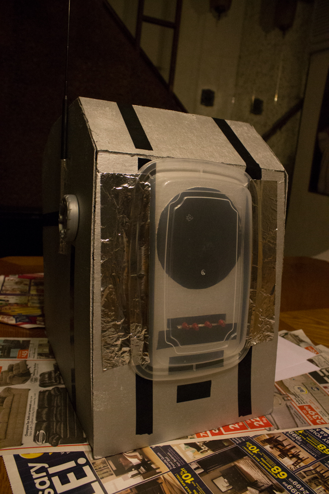
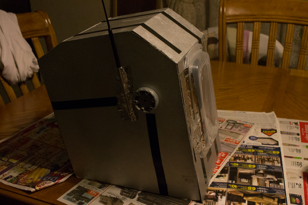
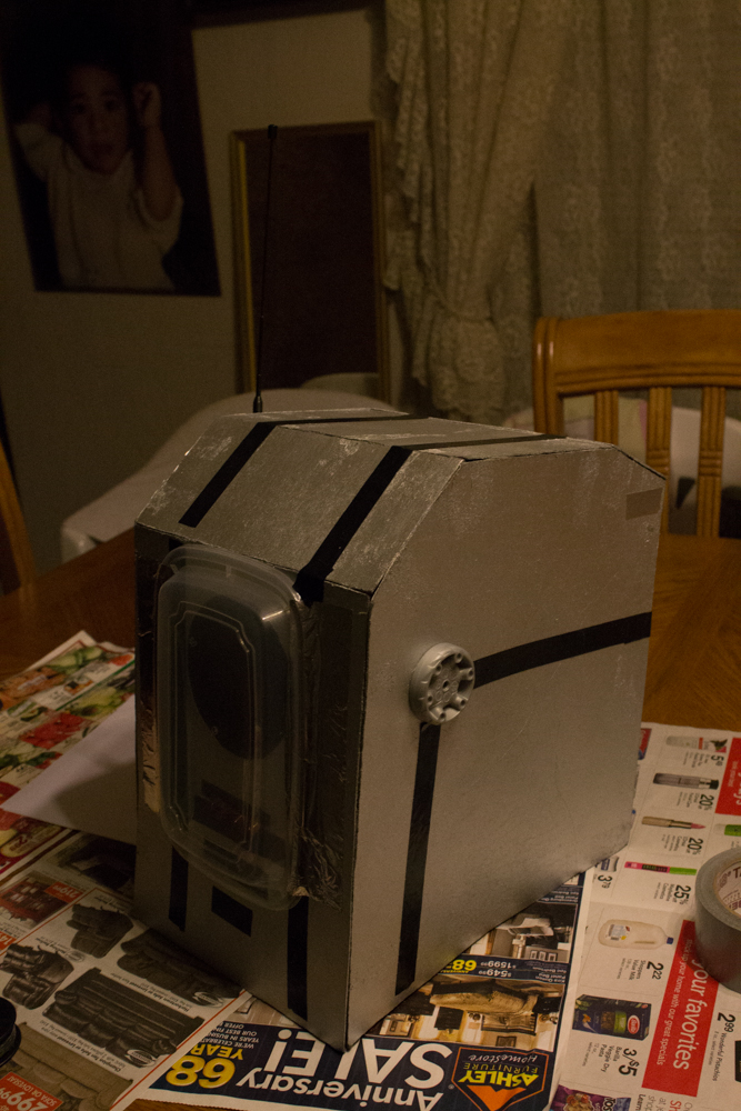
The helmet was made to be large enough to hold my components but small enough so it wouldn’t look comically over sized. It took three tries to get it right.
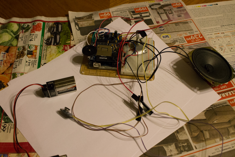
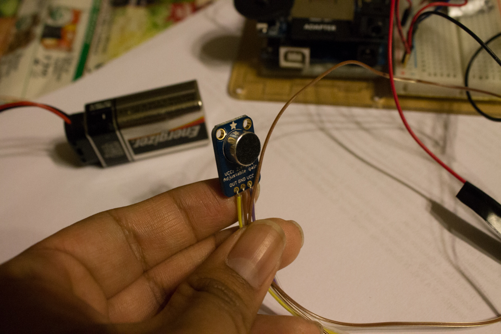
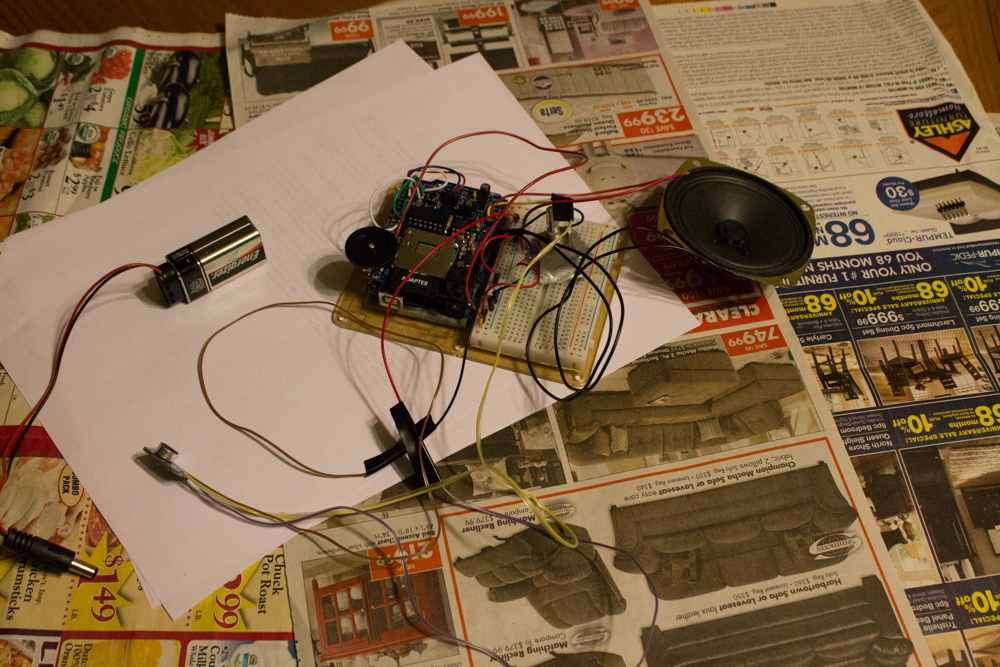
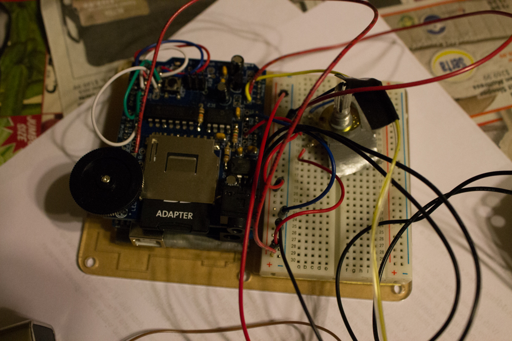
Ah the wave shield and microphone. These parts costed me the most time but they were also the most essential. The beauty of this voice changer was in how customizeable it is. Originally the voice changer tutorial asked for a 6 button matrix, an adapter for ipod like speakers and a seperate powersource for the device. Yet i streamlined it by only having the wave shield, the microphone, and the speaker. I would have left out the 10k pot but i decided to keep it in so i could easily change the pitch of the voice changer. Unfortunately, making it portable was a doozy but i managed to fit it inside the helmet. The last major change was that i extended the microphones reach by adding cable length to bring it as close to my mouth as possible.
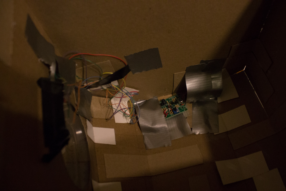
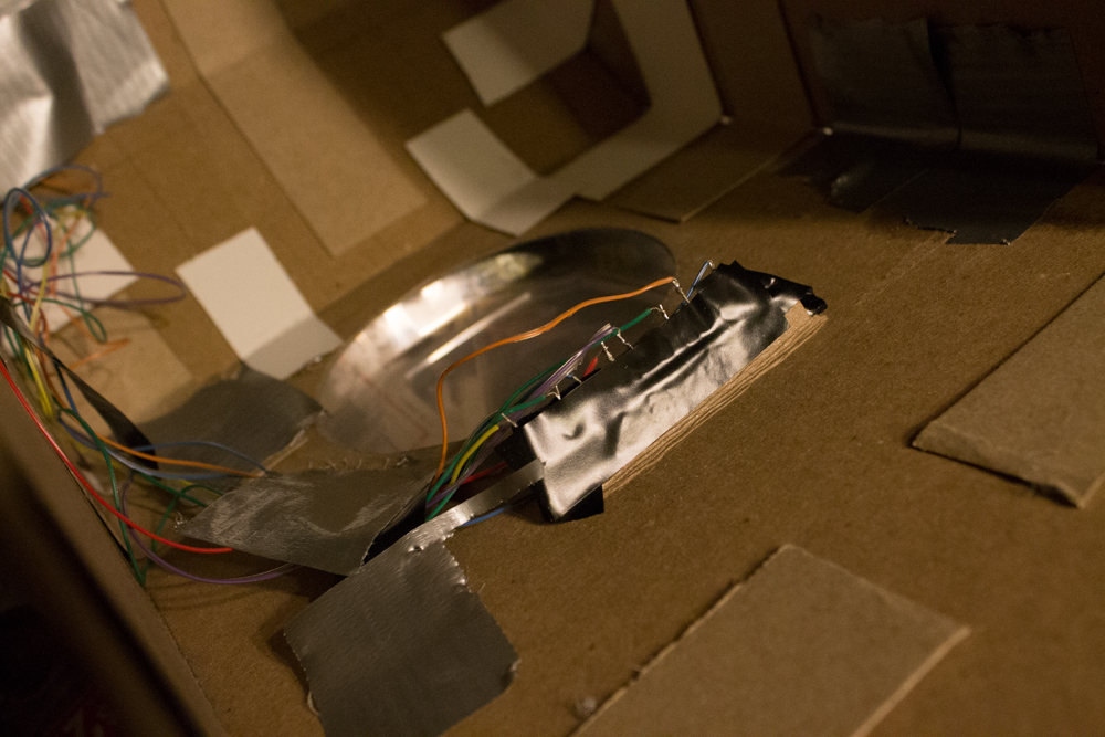
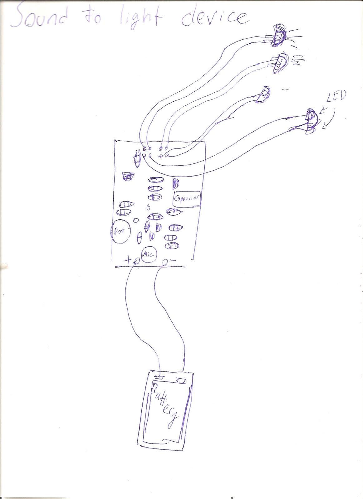
Here we see the sound to light kit with a few modifications (not easily seen here). The main changes were through its actual construction rather than its coding (as it uses no code). The LED’s, previously attached to the kit have been given added cable length to allow the LED’s to be placed where the mouth is. The other benefit of this extension was that it allowed the microphone to be farther away from the voice changer mic which prevented horrible feedback.
Here’s the code:
#include <WaveHC.h>
#include <WaveUtil.h>
SdReader card; // This object holds the information for the card
FatVolume vol; // This holds the information for the partition on the card
FatReader root; // This holds the information for the volumes root directory
FatReader file; // This object represent the WAV file for a pi digit or period
WaveHC wave; // This is the only wave (audio) object, — we only play one at a time
#define error(msg) error_P(PSTR(msg)) // Macro allows error messages in flash memory
#define ADC_CHANNEL 0 // Microphone on Analog pin 0
// Wave shield DAC: digital pins 2, 3, 4, 5
#define DAC_CS_PORT PORTD
#define DAC_CS PORTD2
#define DAC_CLK_PORT PORTD
#define DAC_CLK PORTD3
#define DAC_DI_PORT PORTD
#define DAC_DI PORTD4
#define DAC_LATCH_PORT PORTD
#define DAC_LATCH PORTD5
uint16_t in = 0, out = 0, xf = 0, nSamples; // Audio sample counters
uint8_t adc_save; // Default ADC mode
// WaveHC didn’t declare it’s working buffers private or static,
// so we can be sneaky and borrow the same RAM for audio sampling!
extern uint8_t
buffer1[PLAYBUFFLEN], // Audio sample LSB
buffer2[PLAYBUFFLEN]; // Audio sample MSB
#define XFADE 16 // Number of samples for cross-fade
#define MAX_SAMPLES (PLAYBUFFLEN – XFADE) // Remaining available audio samples
// Keypad information:
uint8_t
rows[] = { A2, A3, A4, A5 }, // Keypad rows connect to these pins
cols[] = { 6, 7, 8 }, // Keypad columns connect to these pins
r = 0, // Current row being examined
prev = 255, // Previous key reading (or 255 if none)
count = 0; // Counter for button debouncing
#define DEBOUNCE 10 // Number of iterations before button ‘takes’
// Keypad/WAV information. Number of elements here should match the
// number of keypad rows times the number of columns, plus one:
const char *sound[] = {
“breath” , “destroy”, “saber” , // Row 1 = Darth Vader sounds
“zilla” , “crunch” , “burp” , // Row 2 = Godzilla sounds
“hithere”, “smell” , “squirrel”, // Row 3 = Dug the dog sounds
“carhorn”, “foghorn”, “door” , // Row 4 = Cartoon/SFX sound
“startup” }; // Extra item = boot sound
//////////////////////////////////// SETUP
void setup() {
uint8_t i;
Serial.begin(9600);
// The WaveHC library normally initializes the DAC pins…but only after
// an SD card is detected and a valid file is passed. Need to init the
// pins manually here so that voice FX works even without a card.
pinMode(2, OUTPUT); // Chip select
pinMode(3, OUTPUT); // Serial clock
pinMode(4, OUTPUT); // Serial data
pinMode(5, OUTPUT); // Latch
digitalWrite(2, HIGH); // Set chip select high
// Init SD library, show root directory. Note that errors are displayed
// but NOT regarded as fatal — the program will continue with voice FX!
if(!card.init()) SerialPrint_P(“Card init. failed!”);
else if(!vol.init(card)) SerialPrint_P(“No partition!”);
else if(!root.openRoot(vol)) SerialPrint_P(“Couldn’t open dir”);
else {
PgmPrintln(“Files found:”);
root.ls();
// Play startup sound (last file in array).
playfile(sizeof(sound) / sizeof(sound[0]) – 1);
}
// Optional, but may make sampling and playback a little smoother:
// Disable Timer0 interrupt. This means delay(), millis() etc. won’t
// work. Comment this out if you really, really need those functions.
TIMSK0 = 0;
// Set up Analog-to-Digital converter:
analogReference(EXTERNAL); // 3.3V to AREF
adc_save = ADCSRA; // Save ADC setting for restore later
// Set keypad rows to outputs, set to HIGH logic level:
for(i=0; i<sizeof(rows); i++) {
pinMode(rows[i], OUTPUT);
digitalWrite(rows[i], HIGH);
}
// Set keypad columns to inputs, enable pull-up resistors:
for(i=0; i<sizeof(cols); i++) {
pinMode(cols[i], INPUT);
digitalWrite(cols[i], HIGH);
}
while(wave.isplaying); // Wait for startup sound to finish…
startPitchShift(); // and start the pitch-shift mode by default.
}
//////////////////////////////////// LOOP
// As written here, the loop function scans a keypad to triggers sounds
// (stopping and restarting the voice effect as needed). If all you need
// is a couple of buttons, it may be easier to tear this out and start
// over with some simple digitalRead() calls.
void loop() {
uint8_t c, button;
// Set current row to LOW logic state…
digitalWrite(rows[r], LOW);
// …then examine column buttons for a match…
for(c=0; c<sizeof(cols); c++) {
if(digitalRead(cols[c]) == LOW) { // First match.
button = r * sizeof(cols) + c; // Get button index.
if(button == prev) { // Same button as before?
if(++count >= DEBOUNCE) { // Yes. Held beyond debounce threshold?
if(wave.isplaying) wave.stop(); // Stop current WAV (if any)
else stopPitchShift(); // or stop voice effect
playfile(button); // and play new sound.
while(digitalRead(cols[c]) == LOW); // Wait for button release.
prev = 255; // Reset debounce values.
count = 0;
}
} else { // Not same button as prior pass.
prev = button; // Record new button and
count = 0; // restart debounce counter.
}
}
}
// Restore current row to HIGH logic state and advance row counter…
digitalWrite(rows[r], HIGH);
if(++r >= sizeof(rows)) { // If last row scanned…
r = 0; // Reset row counter
// If no new sounds have been triggered at this point, and if the
// pitch-shifter is not running, re-start it…
if(!wave.isplaying && !(TIMSK2 & _BV(TOIE2))) startPitchShift();
}
}
//////////////////////////////////// HELPERS
// Open and start playing a WAV file
void playfile(int idx) {
char filename[13];
(void)sprintf(filename,”%s.wav”, sound[idx]);
Serial.print(“File: “);
Serial.println(filename);
if(!file.open(root, filename)) {
PgmPrint(“Couldn’t open file “);
Serial.print(filename);
return;
}
if(!wave.create(file)) {
PgmPrintln(“Not a valid WAV”);
return;
}
wave.play();
}
//////////////////////////////////// PITCH-SHIFT CODE
void startPitchShift() {
// Read analog pitch setting before starting audio sampling:
int pitch = analogRead(1);
Serial.print(“Pitch: “);
Serial.println(pitch);
// Right now the sketch just uses a fixed sound buffer length of
// 128 samples. It may be the case that the buffer length should
// vary with pitch for better results…further experimentation
// is required here.
nSamples = 128;
//nSamples = F_CPU / 3200 / OCR2A; // ???
//if(nSamples > MAX_SAMPLES) nSamples = MAX_SAMPLES;
//else if(nSamples < (XFADE * 2)) nSamples = XFADE * 2;
memset(buffer1, 0, nSamples + XFADE); // Clear sample buffers
memset(buffer2, 2, nSamples + XFADE); // (set all samples to 512)
// WaveHC library already defines a Timer1 interrupt handler. Since we
// want to use the stock library and not require a special fork, Timer2
// is used for a sample-playing interrupt here. As it’s only an 8-bit
// timer, a sizeable prescaler is used (32:1) to generate intervals
// spanning the desired range (~4.8 KHz to ~19 KHz, or +/- 1 octave
// from the sampling frequency). This does limit the available number
// of speed ‘steps’ in between (about 79 total), but seems enough.
TCCR2A = _BV(WGM21) | _BV(WGM20); // Mode 7 (fast PWM), OC2 disconnected
TCCR2B = _BV(WGM22) | _BV(CS21) | _BV(CS20); // 32:1 prescale
OCR2A = map(pitch, 0, 1023,
F_CPU / 32 / (9615 / 2), // Lowest pitch = -1 octave
F_CPU / 32 / (9615 * 2)); // Highest pitch = +1 octave
// Start up ADC in free-run mode for audio sampling:
DIDR0 |= _BV(ADC0D); // Disable digital input buffer on ADC0
ADMUX = ADC_CHANNEL; // Channel sel, right-adj, AREF to 3.3V regulator
ADCSRB = 0; // Free-run mode
ADCSRA = _BV(ADEN) | // Enable ADC
_BV(ADSC) | // Start conversions
_BV(ADATE) | // Auto-trigger enable
_BV(ADIE) | // Interrupt enable
_BV(ADPS2) | // 128:1 prescale…
_BV(ADPS1) | // …yields 125 KHz ADC clock…
_BV(ADPS0); // …13 cycles/conversion = ~9615 Hz
TIMSK2 |= _BV(TOIE2); // Enable Timer2 overflow interrupt
sei(); // Enable interrupts
}
void stopPitchShift() {
ADCSRA = adc_save; // Disable ADC interrupt and allow normal use
TIMSK2 = 0; // Disable Timer2 Interrupt
}
ISR(ADC_vect, ISR_BLOCK) { // ADC conversion complete
// Save old sample from ‘in’ position to xfade buffer:
buffer1[nSamples + xf] = buffer1[in];
buffer2[nSamples + xf] = buffer2[in];
if(++xf >= XFADE) xf = 0;
// Store new value in sample buffers:
buffer1[in] = ADCL; // MUST read ADCL first!
buffer2[in] = ADCH;
if(++in >= nSamples) in = 0;
}
ISR(TIMER2_OVF_vect) { // Playback interrupt
uint16_t s;
uint8_t w, inv, hi, lo, bit;
int o2, i2, pos;
// Cross fade around circular buffer ‘seam’.
if((o2 = (int)out) == (i2 = (int)in)) {
// Sample positions coincide. Use cross-fade buffer data directly.
pos = nSamples + xf;
hi = (buffer2[pos] << 2) | (buffer1[pos] >> 6); // Expand 10-bit data
lo = (buffer1[pos] << 2) | buffer2[pos]; // to 12 bits
} if((o2 < i2) && (o2 > (i2 – XFADE))) {
// Output sample is close to end of input samples. Cross-fade to
// avoid click. The shift operations here assume that XFADE is 16;
// will need adjustment if that changes.
w = in – out; // Weight of sample (1-n)
inv = XFADE – w; // Weight of xfade
pos = nSamples + ((inv + xf) % XFADE);
s = ((buffer2[out] << 8) | buffer1[out]) * w +
((buffer2[pos] << 8) | buffer1[pos]) * inv;
hi = s >> 10; // Shift 14 bit result
lo = s >> 2; // down to 12 bits
} else if (o2 > (i2 + nSamples – XFADE)) {
// More cross-fade condition
w = in + nSamples – out;
inv = XFADE – w;
pos = nSamples + ((inv + xf) % XFADE);
s = ((buffer2[out] << 8) | buffer1[out]) * w +
((buffer2[pos] << 8) | buffer1[pos]) * inv;
hi = s >> 10; // Shift 14 bit result
lo = s >> 2; // down to 12 bits
} else {
// Input and output counters don’t coincide — just use sample directly.
hi = (buffer2[out] << 2) | (buffer1[out] >> 6); // Expand 10-bit data
lo = (buffer1[out] << 2) | buffer2[out]; // to 12 bits
}
// Might be possible to tweak ‘hi’ and ‘lo’ at this point to achieve
// different voice modulations — robot effect, etc.?
DAC_CS_PORT &= ~_BV(DAC_CS); // Select DAC
// Clock out 4 bits DAC config (not in loop because it’s constant)
DAC_DI_PORT &= ~_BV(DAC_DI); // 0 = Select DAC A, unbuffered
DAC_CLK_PORT |= _BV(DAC_CLK); DAC_CLK_PORT &= ~_BV(DAC_CLK);
DAC_CLK_PORT |= _BV(DAC_CLK); DAC_CLK_PORT &= ~_BV(DAC_CLK);
DAC_DI_PORT |= _BV(DAC_DI); // 1X gain, enable = 1
DAC_CLK_PORT |= _BV(DAC_CLK); DAC_CLK_PORT &= ~_BV(DAC_CLK);
DAC_CLK_PORT |= _BV(DAC_CLK); DAC_CLK_PORT &= ~_BV(DAC_CLK);
for(bit=0x08; bit; bit>>=1) { // Clock out first 4 bits of data
if(hi & bit) DAC_DI_PORT |= _BV(DAC_DI);
else DAC_DI_PORT &= ~_BV(DAC_DI);
DAC_CLK_PORT |= _BV(DAC_CLK); DAC_CLK_PORT &= ~_BV(DAC_CLK);
}
for(bit=0x80; bit; bit>>=1) { // Clock out last 8 bits of data
if(lo & bit) DAC_DI_PORT |= _BV(DAC_DI);
else DAC_DI_PORT &= ~_BV(DAC_DI);
DAC_CLK_PORT |= _BV(DAC_CLK); DAC_CLK_PORT &= ~_BV(DAC_CLK);
}
DAC_CS_PORT |= _BV(DAC_CS); // Unselect DAC
if(++out >= nSamples) out = 0;
}
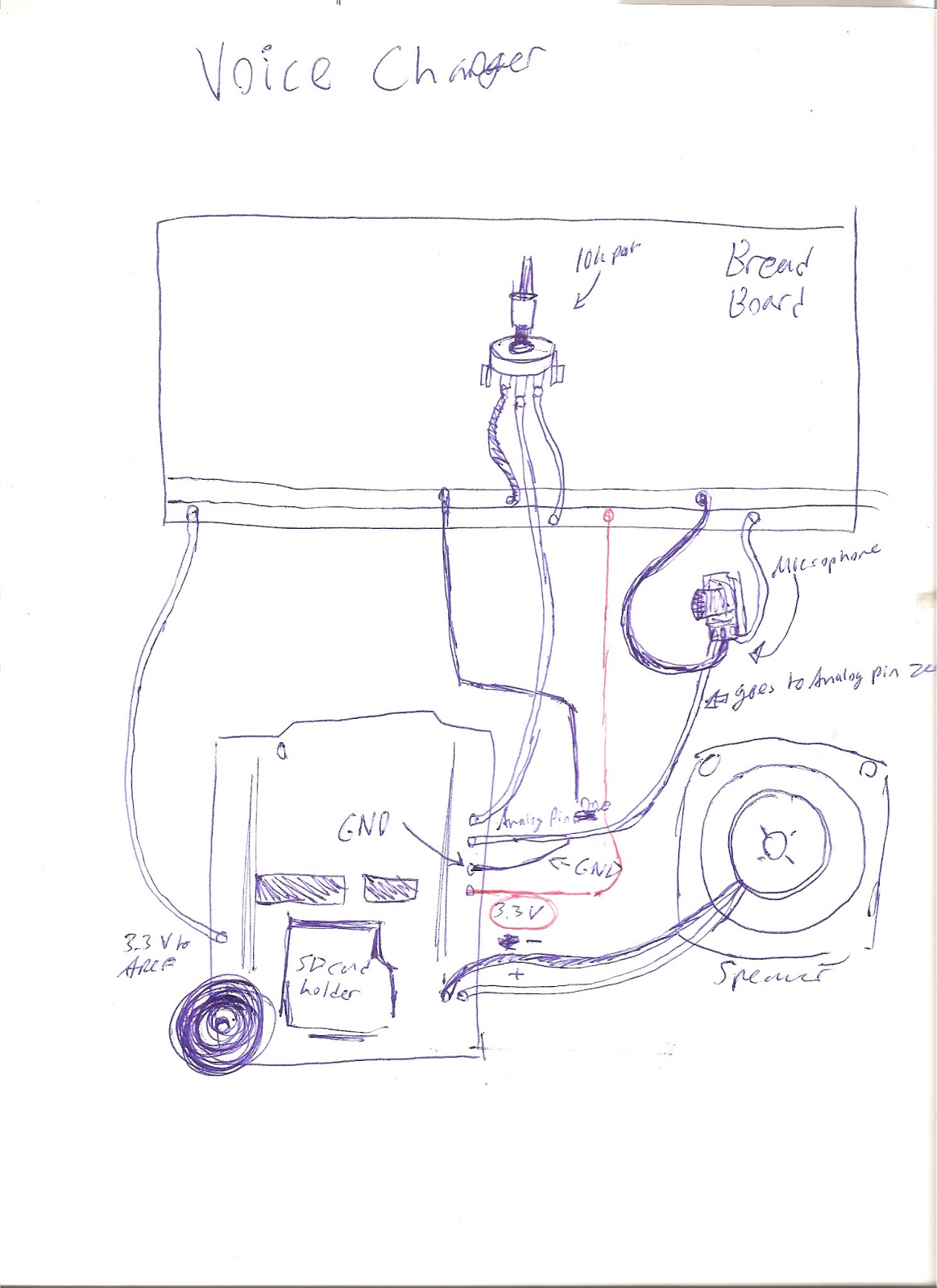
Here’s the circuit diagram