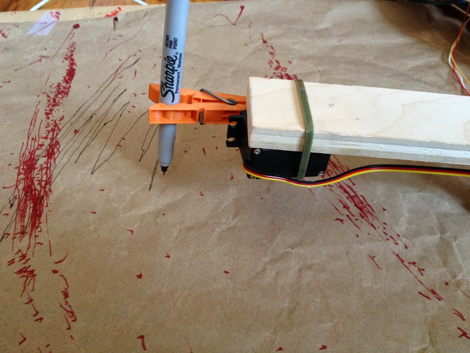
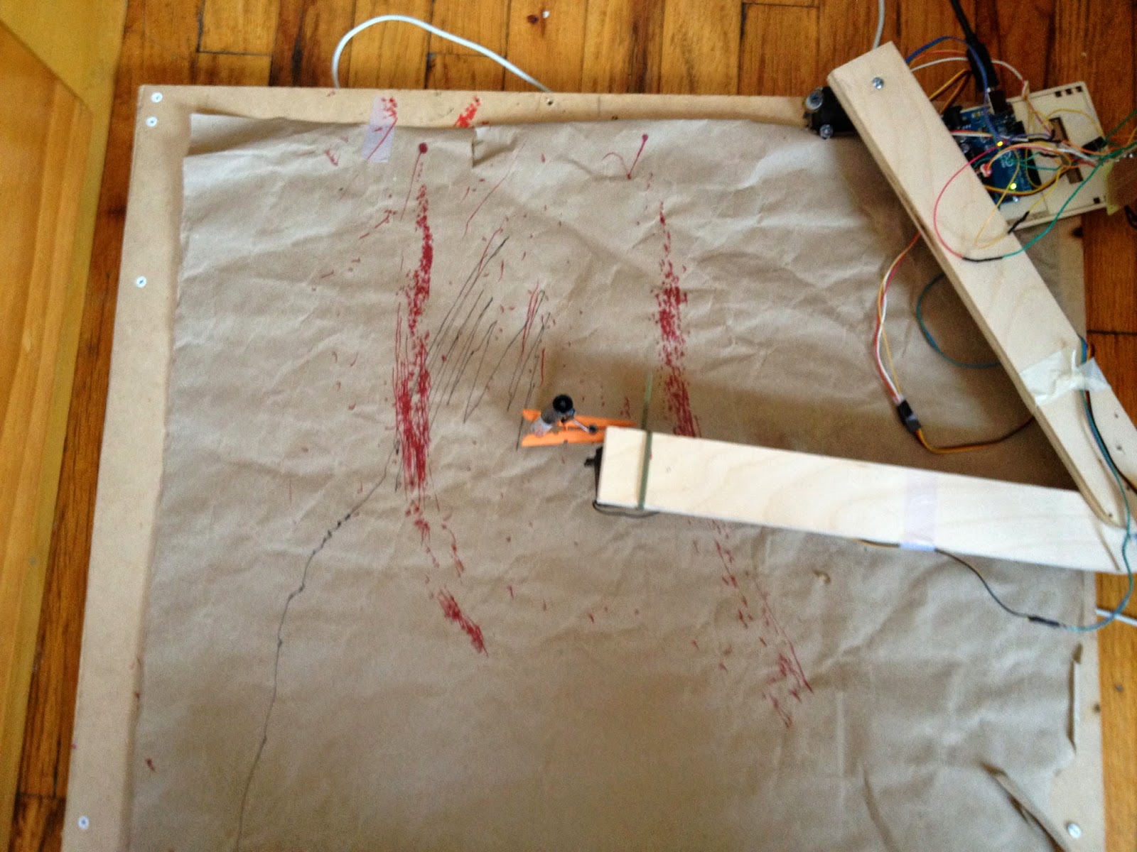
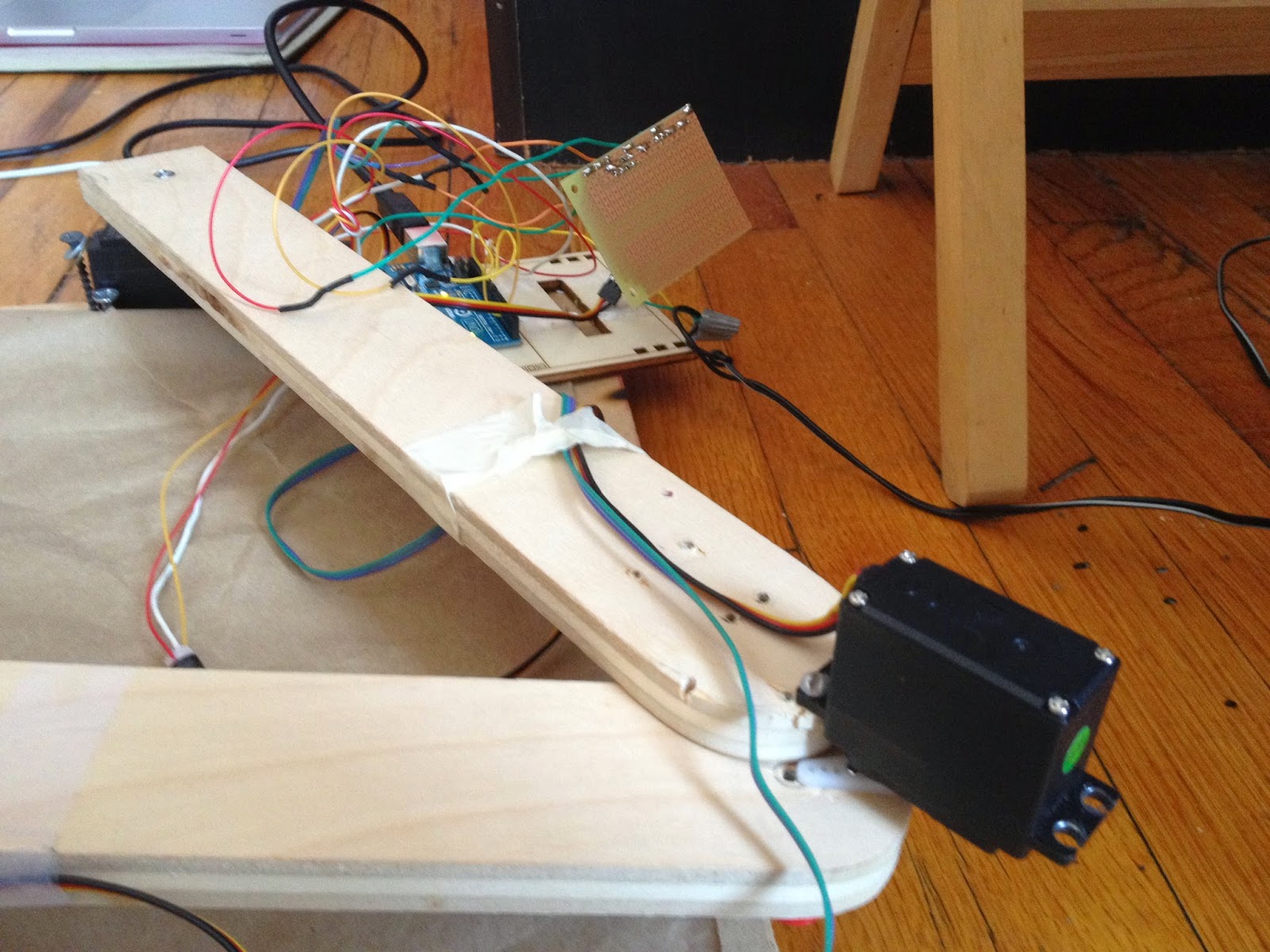
The final project
https://www.dropbox.com/s/dy0o84ua06el9lv/Sequence%2001.mpeg
The image uploaded to processing to be drawn by the drawing machine.

First the Arduino code needs to be used:( can also be found under Examples in Arduino library)
/*
* Firmata is a generic protocol for communicating with microcontrollers
* from software on a host computer. It is intended to work with
* any host computer software package.
*
* To download a host software package, please clink on the following link
* to open the download page in your default browser.
*
* http://firmata.org/wiki/Download
*/
/*
Copyright (C) 2006-2008 Hans-Christoph Steiner. All rights reserved.
Copyright (C) 2010-2011 Paul Stoffregen. All rights reserved.
Copyright (C) 2009 Shigeru Kobayashi. All rights reserved.
Copyright (C) 2009-2011 Jeff Hoefs. All rights reserved.
This library is free software; you can redistribute it and/or
modify it under the terms of the GNU Lesser General Public
License as published by the Free Software Foundation; either
version 2.1 of the License, or (at your option) any later version.
See file LICENSE.txt for further informations on licensing terms.
formatted using the GNU C formatting and indenting
*/
/*
* TODO: use Program Control to load stored profiles from EEPROM
*/
#include <Servo.h>
#include <Wire.h>
#include <Firmata.h>
// move the following defines to Firmata.h?
#define I2C_WRITE B00000000
#define I2C_READ B00001000
#define I2C_READ_CONTINUOUSLY B00010000
#define I2C_STOP_READING B00011000
#define I2C_READ_WRITE_MODE_MASK B00011000
#define I2C_10BIT_ADDRESS_MODE_MASK B00100000
#define MAX_QUERIES 8
#define MINIMUM_SAMPLING_INTERVAL 10
#define REGISTER_NOT_SPECIFIED -1
/*==============================================================================
* GLOBAL VARIABLES
*============================================================================*/
/* analog inputs */
int analogInputsToReport = 0; // bitwise array to store pin reporting
/* digital input ports */
byte reportPINs[TOTAL_PORTS]; // 1 = report this port, 0 = silence
byte previousPINs[TOTAL_PORTS]; // previous 8 bits sent
/* pins configuration */
byte pinConfig[TOTAL_PINS]; // configuration of every pin
byte portConfigInputs[TOTAL_PORTS]; // each bit: 1 = pin in INPUT, 0 = anything else
int pinState[TOTAL_PINS]; // any value that has been written
/* timer variables */
unsigned long currentMillis; // store the current value from millis()
unsigned long previousMillis; // for comparison with currentMillis
int samplingInterval = 19; // how often to run the main loop (in ms)
/* i2c data */
struct i2c_device_info {
byte addr;
byte reg;
byte bytes;
};
/* for i2c read continuous more */
i2c_device_info query[MAX_QUERIES];
byte i2cRxData[32];
boolean isI2CEnabled = false;
signed char queryIndex = -1;
unsigned int i2cReadDelayTime = 0; // default delay time between i2c read request and Wire.requestFrom()
Servo servos[MAX_SERVOS];
/*==============================================================================
* FUNCTIONS
*============================================================================*/
void readAndReportData(byte address, int theRegister, byte numBytes) {
// allow I2C requests that don’t require a register read
// for example, some devices using an interrupt pin to signify new data available
// do not always require the register read so upon interrupt you call Wire.requestFrom()
if (theRegister != REGISTER_NOT_SPECIFIED) {
Wire.beginTransmission(address);
#if ARDUINO >= 100
Wire.write((byte)theRegister);
#else
Wire.send((byte)theRegister);
#endif
Wire.endTransmission();
delayMicroseconds(i2cReadDelayTime); // delay is necessary for some devices such as WiiNunchuck
} else {
theRegister = 0; // fill the register with a dummy value
}
Wire.requestFrom(address, numBytes); // all bytes are returned in requestFrom
// check to be sure correct number of bytes were returned by slave
if(numBytes == Wire.available()) {
i2cRxData[0] = address;
i2cRxData[1] = theRegister;
for (int i = 0; i < numBytes; i++) {
#if ARDUINO >= 100
i2cRxData[2 + i] = Wire.read();
#else
i2cRxData[2 + i] = Wire.receive();
#endif
}
}
else {
if(numBytes > Wire.available()) {
Firmata.sendString(“I2C Read Error: Too many bytes received”);
} else {
Firmata.sendString(“I2C Read Error: Too few bytes received”);
}
}
// send slave address, register and received bytes
Firmata.sendSysex(SYSEX_I2C_REPLY, numBytes + 2, i2cRxData);
}
void outputPort(byte portNumber, byte portValue, byte forceSend)
{
// pins not configured as INPUT are cleared to zeros
portValue = portValue & portConfigInputs[portNumber];
// only send if the value is different than previously sent
if(forceSend || previousPINs[portNumber] != portValue) {
Firmata.sendDigitalPort(portNumber, portValue);
previousPINs[portNumber] = portValue;
}
}
/* —————————————————————————–
* check all the active digital inputs for change of state, then add any events
* to the Serial output queue using Serial.print() */
void checkDigitalInputs(void)
{
/* Using non-looping code allows constants to be given to readPort().
* The compiler will apply substantial optimizations if the inputs
* to readPort() are compile-time constants. */
if (TOTAL_PORTS > 0 && reportPINs[0]) outputPort(0, readPort(0, portConfigInputs[0]), false);
if (TOTAL_PORTS > 1 && reportPINs[1]) outputPort(1, readPort(1, portConfigInputs[1]), false);
if (TOTAL_PORTS > 2 && reportPINs[2]) outputPort(2, readPort(2, portConfigInputs[2]), false);
if (TOTAL_PORTS > 3 && reportPINs[3]) outputPort(3, readPort(3, portConfigInputs[3]), false);
if (TOTAL_PORTS > 4 && reportPINs[4]) outputPort(4, readPort(4, portConfigInputs[4]), false);
if (TOTAL_PORTS > 5 && reportPINs[5]) outputPort(5, readPort(5, portConfigInputs[5]), false);
if (TOTAL_PORTS > 6 && reportPINs[6]) outputPort(6, readPort(6, portConfigInputs[6]), false);
if (TOTAL_PORTS > 7 && reportPINs[7]) outputPort(7, readPort(7, portConfigInputs[7]), false);
if (TOTAL_PORTS > 8 && reportPINs[8]) outputPort(8, readPort(8, portConfigInputs[8]), false);
if (TOTAL_PORTS > 9 && reportPINs[9]) outputPort(9, readPort(9, portConfigInputs[9]), false);
if (TOTAL_PORTS > 10 && reportPINs[10]) outputPort(10, readPort(10, portConfigInputs[10]), false);
if (TOTAL_PORTS > 11 && reportPINs[11]) outputPort(11, readPort(11, portConfigInputs[11]), false);
if (TOTAL_PORTS > 12 && reportPINs[12]) outputPort(12, readPort(12, portConfigInputs[12]), false);
if (TOTAL_PORTS > 13 && reportPINs[13]) outputPort(13, readPort(13, portConfigInputs[13]), false);
if (TOTAL_PORTS > 14 && reportPINs[14]) outputPort(14, readPort(14, portConfigInputs[14]), false);
if (TOTAL_PORTS > 15 && reportPINs[15]) outputPort(15, readPort(15, portConfigInputs[15]), false);
}
// —————————————————————————–
/* sets the pin mode to the correct state and sets the relevant bits in the
* two bit-arrays that track Digital I/O and PWM status
*/
void setPinModeCallback(byte pin, int mode)
{
if (pinConfig[pin] == I2C && isI2CEnabled && mode != I2C) {
// disable i2c so pins can be used for other functions
// the following if statements should reconfigure the pins properly
disableI2CPins();
}
if (IS_PIN_SERVO(pin) && mode != SERVO && servos[PIN_TO_SERVO(pin)].attached()) {
servos[PIN_TO_SERVO(pin)].detach();
}
if (IS_PIN_ANALOG(pin)) {
reportAnalogCallback(PIN_TO_ANALOG(pin), mode == ANALOG ? 1 : 0); // turn on/off reporting
}
if (IS_PIN_DIGITAL(pin)) {
if (mode == INPUT) {
portConfigInputs[pin/8] |= (1 << (pin & 7));
} else {
portConfigInputs[pin/8] &= ~(1 << (pin & 7));
}
}
pinState[pin] = 0;
switch(mode) {
case ANALOG:
if (IS_PIN_ANALOG(pin)) {
if (IS_PIN_DIGITAL(pin)) {
pinMode(PIN_TO_DIGITAL(pin), INPUT); // disable output driver
digitalWrite(PIN_TO_DIGITAL(pin), LOW); // disable internal pull-ups
}
pinConfig[pin] = ANALOG;
}
break;
case INPUT:
if (IS_PIN_DIGITAL(pin)) {
pinMode(PIN_TO_DIGITAL(pin), INPUT); // disable output driver
digitalWrite(PIN_TO_DIGITAL(pin), LOW); // disable internal pull-ups
pinConfig[pin] = INPUT;
}
break;
case OUTPUT:
if (IS_PIN_DIGITAL(pin)) {
digitalWrite(PIN_TO_DIGITAL(pin), LOW); // disable PWM
pinMode(PIN_TO_DIGITAL(pin), OUTPUT);
pinConfig[pin] = OUTPUT;
}
break;
case PWM:
if (IS_PIN_PWM(pin)) {
pinMode(PIN_TO_PWM(pin), OUTPUT);
analogWrite(PIN_TO_PWM(pin), 0);
pinConfig[pin] = PWM;
}
break;
case SERVO:
if (IS_PIN_SERVO(pin)) {
pinConfig[pin] = SERVO;
if (!servos[PIN_TO_SERVO(pin)].attached()) {
servos[PIN_TO_SERVO(pin)].attach(PIN_TO_DIGITAL(pin));
}
}
break;
case I2C:
if (IS_PIN_I2C(pin)) {
// mark the pin as i2c
// the user must call I2C_CONFIG to enable I2C for a device
pinConfig[pin] = I2C;
}
break;
default:
Firmata.sendString(“Unknown pin mode”); // TODO: put error msgs in EEPROM
}
// TODO: save status to EEPROM here, if changed
}
void analogWriteCallback(byte pin, int value)
{
if (pin < TOTAL_PINS) {
switch(pinConfig[pin]) {
case SERVO:
if (IS_PIN_SERVO(pin))
servos[PIN_TO_SERVO(pin)].write(value);
pinState[pin] = value;
break;
case PWM:
if (IS_PIN_PWM(pin))
analogWrite(PIN_TO_PWM(pin), value);
pinState[pin] = value;
break;
}
}
}
void digitalWriteCallback(byte port, int value)
{
byte pin, lastPin, mask=1, pinWriteMask=0;
if (port < TOTAL_PORTS) {
// create a mask of the pins on this port that are writable.
lastPin = port*8+8;
if (lastPin > TOTAL_PINS) lastPin = TOTAL_PINS;
for (pin=port*8; pin < lastPin; pin++) {
// do not disturb non-digital pins (eg, Rx & Tx)
if (IS_PIN_DIGITAL(pin)) {
// only write to OUTPUT and INPUT (enables pullup)
// do not touch pins in PWM, ANALOG, SERVO or other modes
if (pinConfig[pin] == OUTPUT || pinConfig[pin] == INPUT) {
pinWriteMask |= mask;
pinState[pin] = ((byte)value & mask) ? 1 : 0;
}
}
mask = mask << 1;
}
writePort(port, (byte)value, pinWriteMask);
}
}
// —————————————————————————–
/* sets bits in a bit array (int) to toggle the reporting of the analogIns
*/
//void FirmataClass::setAnalogPinReporting(byte pin, byte state) {
//}
void reportAnalogCallback(byte analogPin, int value)
{
if (analogPin < TOTAL_ANALOG_PINS) {
if(value == 0) {
analogInputsToReport = analogInputsToReport &~ (1 << analogPin);
} else {
analogInputsToReport = analogInputsToReport | (1 << analogPin);
}
}
// TODO: save status to EEPROM here, if changed
}
void reportDigitalCallback(byte port, int value)
{
if (port < TOTAL_PORTS) {
reportPINs[port] = (byte)value;
}
// do not disable analog reporting on these 8 pins, to allow some
// pins used for digital, others analog. Instead, allow both types
// of reporting to be enabled, but check if the pin is configured
// as analog when sampling the analog inputs. Likewise, while
// scanning digital pins, portConfigInputs will mask off values from any
// pins configured as analog
}
/*==============================================================================
* SYSEX-BASED commands
*============================================================================*/
void sysexCallback(byte command, byte argc, byte *argv)
{
byte mode;
byte slaveAddress;
byte slaveRegister;
byte data;
unsigned int delayTime;
switch(command) {
case I2C_REQUEST:
mode = argv[1] & I2C_READ_WRITE_MODE_MASK;
if (argv[1] & I2C_10BIT_ADDRESS_MODE_MASK) {
Firmata.sendString(“10-bit addressing mode is not yet supported”);
return;
}
else {
slaveAddress = argv[0];
}
switch(mode) {
case I2C_WRITE:
Wire.beginTransmission(slaveAddress);
for (byte i = 2; i < argc; i += 2) {
data = argv[i] + (argv[i + 1] << 7);
#if ARDUINO >= 100
Wire.write(data);
#else
Wire.send(data);
#endif
}
Wire.endTransmission();
delayMicroseconds(70);
break;
case I2C_READ:
if (argc == 6) {
// a slave register is specified
slaveRegister = argv[2] + (argv[3] << 7);
data = argv[4] + (argv[5] << 7); // bytes to read
readAndReportData(slaveAddress, (int)slaveRegister, data);
}
else {
// a slave register is NOT specified
data = argv[2] + (argv[3] << 7); // bytes to read
readAndReportData(slaveAddress, (int)REGISTER_NOT_SPECIFIED, data);
}
break;
case I2C_READ_CONTINUOUSLY:
if ((queryIndex + 1) >= MAX_QUERIES) {
// too many queries, just ignore
Firmata.sendString(“too many queries”);
break;
}
queryIndex++;
query[queryIndex].addr = slaveAddress;
query[queryIndex].reg = argv[2] + (argv[3] << 7);
query[queryIndex].bytes = argv[4] + (argv[5] << 7);
break;
case I2C_STOP_READING:
byte queryIndexToSkip;
// if read continuous mode is enabled for only 1 i2c device, disable
// read continuous reporting for that device
if (queryIndex <= 0) {
queryIndex = -1;
} else {
// if read continuous mode is enabled for multiple devices,
// determine which device to stop reading and remove it’s data from
// the array, shifiting other array data to fill the space
for (byte i = 0; i < queryIndex + 1; i++) {
if (query[i].addr = slaveAddress) {
queryIndexToSkip = i;
break;
}
}
for (byte i = queryIndexToSkip; i<queryIndex + 1; i++) {
if (i < MAX_QUERIES) {
query[i].addr = query[i+1].addr;
query[i].reg = query[i+1].addr;
query[i].bytes = query[i+1].bytes;
}
}
queryIndex–;
}
break;
default:
break;
}
break;
case I2C_CONFIG:
delayTime = (argv[0] + (argv[1] << 7));
if(delayTime > 0) {
i2cReadDelayTime = delayTime;
}
if (!isI2CEnabled) {
enableI2CPins();
}
break;
case SERVO_CONFIG:
if(argc > 4) {
// these vars are here for clarity, they’ll optimized away by the compiler
byte pin = argv[0];
int minPulse = argv[1] + (argv[2] << 7);
int maxPulse = argv[3] + (argv[4] << 7);
if (IS_PIN_SERVO(pin)) {
if (servos[PIN_TO_SERVO(pin)].attached())
servos[PIN_TO_SERVO(pin)].detach();
servos[PIN_TO_SERVO(pin)].attach(PIN_TO_DIGITAL(pin), minPulse, maxPulse);
setPinModeCallback(pin, SERVO);
}
}
break;
case SAMPLING_INTERVAL:
if (argc > 1) {
samplingInterval = argv[0] + (argv[1] << 7);
if (samplingInterval < MINIMUM_SAMPLING_INTERVAL) {
samplingInterval = MINIMUM_SAMPLING_INTERVAL;
}
} else {
//Firmata.sendString(“Not enough data”);
}
break;
case EXTENDED_ANALOG:
if (argc > 1) {
int val = argv[1];
if (argc > 2) val |= (argv[2] << 7);
if (argc > 3) val |= (argv[3] << 14);
analogWriteCallback(argv[0], val);
}
break;
case CAPABILITY_QUERY:
Serial.write(START_SYSEX);
Serial.write(CAPABILITY_RESPONSE);
for (byte pin=0; pin < TOTAL_PINS; pin++) {
if (IS_PIN_DIGITAL(pin)) {
Serial.write((byte)INPUT);
Serial.write(1);
Serial.write((byte)OUTPUT);
Serial.write(1);
}
if (IS_PIN_ANALOG(pin)) {
Serial.write(ANALOG);
Serial.write(10);
}
if (IS_PIN_PWM(pin)) {
Serial.write(PWM);
Serial.write(8);
}
if (IS_PIN_SERVO(pin)) {
Serial.write(SERVO);
Serial.write(14);
}
if (IS_PIN_I2C(pin)) {
Serial.write(I2C);
Serial.write(1); // to do: determine appropriate value
}
Serial.write(127);
}
Serial.write(END_SYSEX);
break;
case PIN_STATE_QUERY:
if (argc > 0) {
byte pin=argv[0];
Serial.write(START_SYSEX);
Serial.write(PIN_STATE_RESPONSE);
Serial.write(pin);
if (pin < TOTAL_PINS) {
Serial.write((byte)pinConfig[pin]);
Serial.write((byte)pinState[pin] & 0x7F);
if (pinState[pin] & 0xFF80) Serial.write((byte)(pinState[pin] >> 7) & 0x7F);
if (pinState[pin] & 0xC000) Serial.write((byte)(pinState[pin] >> 14) & 0x7F);
}
Serial.write(END_SYSEX);
}
break;
case ANALOG_MAPPING_QUERY:
Serial.write(START_SYSEX);
Serial.write(ANALOG_MAPPING_RESPONSE);
for (byte pin=0; pin < TOTAL_PINS; pin++) {
Serial.write(IS_PIN_ANALOG(pin) ? PIN_TO_ANALOG(pin) : 127);
}
Serial.write(END_SYSEX);
break;
}
}
void enableI2CPins()
{
byte i;
// is there a faster way to do this? would probaby require importing
// Arduino.h to get SCL and SDA pins
for (i=0; i < TOTAL_PINS; i++) {
if(IS_PIN_I2C(i)) {
// mark pins as i2c so they are ignore in non i2c data requests
setPinModeCallback(i, I2C);
}
}
isI2CEnabled = true;
// is there enough time before the first I2C request to call this here?
Wire.begin();
}
/* disable the i2c pins so they can be used for other functions */
void disableI2CPins() {
isI2CEnabled = false;
// disable read continuous mode for all devices
queryIndex = -1;
// uncomment the following if or when the end() method is added to Wire library
// Wire.end();
}
/*==============================================================================
* SETUP()
*============================================================================*/
void systemResetCallback()
{
// initialize a defalt state
// TODO: option to load config from EEPROM instead of default
if (isI2CEnabled) {
disableI2CPins();
}
for (byte i=0; i < TOTAL_PORTS; i++) {
reportPINs[i] = false; // by default, reporting off
portConfigInputs[i] = 0; // until activated
previousPINs[i] = 0;
}
// pins with analog capability default to analog input
// otherwise, pins default to digital output
for (byte i=0; i < TOTAL_PINS; i++) {
if (IS_PIN_ANALOG(i)) {
// turns off pullup, configures everything
setPinModeCallback(i, ANALOG);
} else {
// sets the output to 0, configures portConfigInputs
setPinModeCallback(i, OUTPUT);
}
}
// by default, do not report any analog inputs
analogInputsToReport = 0;
/* send digital inputs to set the initial state on the host computer,
* since once in the loop(), this firmware will only send on change */
/*
TODO: this can never execute, since no pins default to digital input
but it will be needed when/if we support EEPROM stored config
for (byte i=0; i < TOTAL_PORTS; i++) {
outputPort(i, readPort(i, portConfigInputs[i]), true);
}
*/
}
void setup()
{
Firmata.setFirmwareVersion(FIRMATA_MAJOR_VERSION, FIRMATA_MINOR_VERSION);
Firmata.attach(ANALOG_MESSAGE, analogWriteCallback);
Firmata.attach(DIGITAL_MESSAGE, digitalWriteCallback);
Firmata.attach(REPORT_ANALOG, reportAnalogCallback);
Firmata.attach(REPORT_DIGITAL, reportDigitalCallback);
Firmata.attach(SET_PIN_MODE, setPinModeCallback);
Firmata.attach(START_SYSEX, sysexCallback);
Firmata.attach(SYSTEM_RESET, systemResetCallback);
Firmata.begin(57600);
systemResetCallback(); // reset to default config
}
/*==============================================================================
* LOOP()
*============================================================================*/
void loop()
{
byte pin, analogPin;
/* DIGITALREAD – as fast as possible, check for changes and output them to the
* FTDI buffer using Serial.print() */
checkDigitalInputs();
/* SERIALREAD – processing incoming messagse as soon as possible, while still
* checking digital inputs. */
while(Firmata.available())
Firmata.processInput();
/* SEND FTDI WRITE BUFFER – make sure that the FTDI buffer doesn’t go over
* 60 bytes. use a timer to sending an event character every 4 ms to
* trigger the buffer to dump. */
currentMillis = millis();
if (currentMillis – previousMillis > samplingInterval) {
previousMillis += samplingInterval;
/* ANALOGREAD – do all analogReads() at the configured sampling interval */
for(pin=0; pin<TOTAL_PINS; pin++) {
if (IS_PIN_ANALOG(pin) && pinConfig[pin] == ANALOG) {
analogPin = PIN_TO_ANALOG(pin);
if (analogInputsToReport & (1 << analogPin)) {
Firmata.sendAnalog(analogPin, analogRead(analogPin));
}
}
}
// report i2c data for all device with read continuous mode enabled
if (queryIndex > -1) {
for (byte i = 0; i < queryIndex + 1; i++) {
readAndReportData(query[i].addr, query[i].reg, query[i].bytes);
}
}
}
}
Below is the code in processing:
import processing.serial.*;
import cc.arduino.*;
Arduino arduino;
int countstart = 0;
// ORIGINAL
/*
int servo1Pin = 9; // Control pin for servo motor
int servo2Pin = 10; // Control pin for servo motor
int servo3Pin = 11; // Control pin for servo motor
*/
/*
digitposn
penposn
armposn
*/
int servo1Pin = 9; // Control pin for servo motor – shoulder
int servo2Pin = 11; // Control pin for servo motor – elbow
int servo3Pin = 10; // Control pin for servo motor – pen
int armposn;// = 0;
int digitposn;// = 0;
//int penposn;//= 0;
int penstate = 0;
int xcent = 300;
int ycent = 300;
//int targetX= 400;
//int targetY= 200;
int line1 = 130;
int line2 = 130;
int minimumlength = 40;
color black = color(0);
PImage img;
PImage edgeImg ;
void setup() {
float[][] kernel = {
{ -1, -1, -1},
{ -1, 9, -1},
{ -1, -1, -1}
};
size (600, 600);
background(255);
img = loadImage(“ben.jpg”); // Load the original image
img.loadPixels();
edgeImg = createImage(img.width, img.height, RGB);
// Loop through every pixel in the image.
for (int y = 1; y < img.height-1; y++) { // Skip top and bottom edges
for (int x = 1; x < img.width-1; x++) { // Skip left and right edges
float sum = 0; // Kernel sum for this pixel
for (int ky = -1; ky <= 1; ky++) {
for (int kx = -1; kx <= 1; kx++) {
// Calculate the adjacent pixel for this kernel point
int pos = (y + ky)*img.width + (x + kx);
// Image is grayscale, red/green/blue are identical
float val = red(img.pixels[pos]);
// Multiply adjacent pixels based on the kernel values
sum += kernel[ky+1][kx+1] * val;
}
}
// For this pixel in the new image, set the gray value
// based on the sum from the kernel
edgeImg.pixels[y*img.width + x] = color(sum);
}
}
// State that there are changes to edgeImg.pixels[]
edgeImg.updatePixels();
arduino = new Arduino(this, Arduino.list()[5]);
arduino.pinMode(servo1Pin, Arduino.OUTPUT);
arduino.pinMode(servo2Pin, Arduino.OUTPUT);
arduino.pinMode(servo3Pin, Arduino.OUTPUT);
arduino.analogWrite(servo1Pin, 70);
arduino.analogWrite(servo2Pin, 170);
arduino.analogWrite(servo3Pin, 50); // the servo moves to the horizontal location of the mouse
// note – we are setting a digital pin to output
background(255);
}
void draw() {
if (countstart == 1) {
println(“in if”);
makepic();
arduino.analogWrite(servo1Pin, 70);
arduino.analogWrite(servo2Pin, 170);
arduino.analogWrite(servo3Pin, 50);
}
countstart = countstart +1;
}
void makepic() {
background(255);
//fill(50);
stroke(0);
//rect(350+30,320-10,130,130);
image(img, 0, 0, 130, 130); // Displays the image from point (0,0)
image(img, 130, 0, 130, 130); // Draw the new image
filter(POSTERIZE, 4);
filter(THRESHOLD);
colorMode(HSB);
for (int xcycle = 130; xcycle < 259; xcycle = xcycle+2) {
for (int ycycle = 0; ycycle < 129; ycycle++) {
if (get(xcycle, ycycle)<-2) {
set(xcycle+350-130+30, ycycle+320-10, black);
markpaper(xcycle+350-130+30, ycycle+320-10, 110);//changed pen variable 110
delay(20);
//markpaper(xcycle+350-130+30, ycycle+320-10, 170);//comment this line and the one further below out to draw lines not dots
//delay(20);
} else {
set(xcycle, ycycle, 0);
markpaper(xcycle+350-130+30, ycycle+320-10, 170);
//delay(50);
}
}
for (int ycycle = 129; ycycle > 0; ycycle–) {
if (get(xcycle+1, ycycle)<-2) {
set(xcycle+350-130+1+30, ycycle+320-10, black);
markpaper(xcycle+350-130+1+30, ycycle+320-10, 110);
//delay(20);
//markpaper(xcycle+350-130+1+30, ycycle+320-10, 170);//likewise comment this line out for lines not dots on your paper as well as the one further up
} else {
set(xcycle+1, ycycle, 0);
markpaper(xcycle+350-130+1+30, ycycle+320-10, 170);
//delay(50);
}
}
}
}
void markpaper(int targetX, int targetY, int penposn) {
// print(“xposn” + targetX);
// println(” yposn” + targetY);
float angle1 = atan2((targetX – xcent), (targetY – ycent));
float sectorlength = sqrt(sq(targetX – xcent)+sq(targetY – ycent));
//if it’s out of reach, shorten the length in the same direction
if (sectorlength > (line1+line2)) {
sectorlength = line1+line2;
targetX = int(xcent + sin(angle1)*sectorlength);
targetY = int(ycent + cos(angle1)*sectorlength);
}
if (sectorlength < minimumlength) {
sectorlength = minimumlength;
targetX = int(xcent + sin(angle1)*sectorlength);
targetY = int(ycent + cos(angle1)*sectorlength);
}
float internangle = acos((sq(sectorlength)-sq(line2)-sq(line1))/(2*line1*line2));
float sendangle1st = (angle1+(internangle/2));
if (degrees(sendangle1st) < 0 ) {
sendangle1st = radians(0);
}
if (degrees(sendangle1st) > 180 ) {
sendangle1st = radians(180);
}
int line1X = int(xcent+ sin(sendangle1st)*line1);
int line1Y = int(ycent+ cos(sendangle1st)*line1);
int line2X = line1X + int(sin(((angle1+(internangle/2) – internangle)))*line2);
int line2Y = line1Y + int(cos(((angle1+(internangle/2) – internangle)))*line2);
stroke(0, 9);
line(xcent, ycent, line1X, line1Y);
line(line1X, line1Y, line2X-1, line2Y-1);
/*if (penposn == 150) {
set(line2X,line2Y,black);
println(“TEXT”);
}
set(mouseX,mouseY,black);*/
//if it’s too close set the minimum threshold in the same direction
int sendangle1 = round(degrees(sendangle1st));
int sendangle2 = round(degrees((radians(180) – internangle)-radians(35)));
//println(“Send1>”+ sendangle1 + ” Send2 >” + sendangle2);
digitposn = sendangle2;
armposn = sendangle1;
arduino.analogWrite(servo1Pin, digitposn);
arduino.analogWrite(servo2Pin, penposn);
arduino.analogWrite(servo3Pin, armposn);
if (penstate != penposn) {
delay(300);
} else {
delay(1);
}// the servo moves to the horizontal location of the mouse
penstate = penposn;
}