#include <Adafruit_NeoPixel.h>
#define N_PIXELS 12 // Number of pixels you are using
#define MIC_PIN 1 // Microphone is attached to Trinket GPIO #2/Gemma D2 (A1)
#define LED_PIN 0 // NeoPixel LED strand is connected to GPIO #0 / D0
#define DC_OFFSET 0 // DC offset in mic signal – if unusure, leave 0
#define NOISE 100 // Noise/hum/interference in mic signal
#define SAMPLES 60 // Length of buffer for dynamic level adjustment
#define TOP (N_PIXELS +1) // Allow dot to go slightly off scale
byte
peak = 0, // Used for falling dot
dotCount = 0, // Frame counter for delaying dot-falling speed
volCount = 0; // Frame counter for storing past volume data
int
vol[SAMPLES], // Collection of prior volume samples
lvl = 10, // Current “dampened” audio level
minLvlAvg = 0, // For dynamic adjustment of graph low & high
maxLvlAvg = 512;
Adafruit_NeoPixel strip = Adafruit_NeoPixel(N_PIXELS, LED_PIN, NEO_GRB + NEO_KHZ800);
void setup() {
memset(vol, 0, sizeof(vol));
strip.begin();
}
void loop() {
uint8_t i;
uint16_t minLvl, maxLvl;
int n, height;
n = analogRead(MIC_PIN); // Raw reading from mic
n = abs(n – 512 – DC_OFFSET); // Center on zero
n = (n <= NOISE) ? 0 : (n – NOISE); // Remove noise/hum
lvl = ((lvl * 7) + n) >> 3; // “Dampened” reading (else looks twitchy)
// Calculate bar height based on dynamic min/max levels (fixed point):
height = TOP * (lvl – minLvlAvg) / (long)(maxLvlAvg – minLvlAvg);
if(height < 0L) height = 0; // Clip output
else if(height > TOP) height = TOP;
if(height > peak) peak = height; // Keep ‘peak’ dot at top
// Color pixels based on rainbow gradient
for(i=0; i<N_PIXELS; i++) {
if(i >= height)
strip.setPixelColor(i, 0, 0, 0);
else
strip.setPixelColor(i,Wheel(map(i,0,strip.numPixels()-1,30,150)));
}
strip.show(); // Update strip
vol[volCount] = n; // Save sample for dynamic leveling
if(++volCount >= SAMPLES) volCount = 0; // Advance/rollover sample counter
// Get volume range of prior frames
minLvl = maxLvl = vol[0];
for(i=1; i<SAMPLES; i++) {
if(vol[i] < minLvl) minLvl = vol[i];
else if(vol[i] > maxLvl) maxLvl = vol[i];
}
// minLvl and maxLvl indicate the volume range over prior frames, used
// for vertically scaling the output graph (so it looks interesting
// regardless of volume level). If they’re too close together though
// (e.g. at very low volume levels) the graph becomes super coarse
// and ‘jumpy’…so keep some minimum distance between them (this
// also lets the graph go to zero when no sound is playing):
if((maxLvl – minLvl) < TOP) maxLvl = minLvl + TOP;
minLvlAvg = (minLvlAvg * 63 + minLvl) >> 6; // Dampen min/max levels
maxLvlAvg = (maxLvlAvg * 63 + maxLvl) >> 6; // (fake rolling average)
}
// Input a value 0 to 255 to get a color value.
// The colors are a transition r – g – b – back to r.
uint32_t Wheel(byte WheelPos) {
if(WheelPos < 85) {
return strip.Color(WheelPos * 3, 255 – WheelPos * 3, 0);
} else if(WheelPos < 170) {
WheelPos -= 85;
return strip.Color(255 – WheelPos * 3, 0, WheelPos * 3);
} else {
WheelPos -= 170;
return strip.Color(0, WheelPos * 3, 255 – WheelPos * 3);
}
}
CODE[Neopixel Strip]
#define N_PIXELS 76 // Number of pixels in strand
#define MIC_PIN A9 // Microphone is attached to this analog pin
#define LED_PIN 6 // NeoPixel LED strand is connected to this pin
#define DC_OFFSET 0 // DC offset in mic signal – if unusure, leave 0
#define NOISE 10 // Noise/hum/interference in mic signal
#define SAMPLES 60 // Length of buffer for dynamic level adjustment
#define TOP (N_PIXELS + 2) // Allow dot to go slightly off scale
#define PEAK_FALL 4 // Rate of peak falling dot
byte
peak = 0, // Used for falling dot
dotCount = 0, // Frame counter for delaying dot-falling speed
volCount = 0; // Frame counter for storing past volume data
int
vol[SAMPLES], // Collection of prior volume samples
lvl = 10, // Current “dampened” audio level
minLvlAvg = 0, // For dynamic adjustment of graph low & high
maxLvlAvg = 512;
Adafruit_NeoPixel
strip = Adafruit_NeoPixel(N_PIXELS, LED_PIN, NEO_GRB + NEO_KHZ800);
void setup() {
// This is only needed on 5V Arduinos (Uno, Leonardo, etc.).
// Connect 3.3V to mic AND TO AREF ON ARDUINO and enable this
// line. Audio samples are ‘cleaner’ at 3.3V.
// COMMENT OUT THIS LINE FOR 3.3V ARDUINOS (FLORA, ETC.):
// analogReference(EXTERNAL);
memset(vol, 0, sizeof(vol));
strip.begin();
}
void loop() {
uint8_t i;
uint16_t minLvl, maxLvl;
int n, height;
n = analogRead(MIC_PIN); // Raw reading from mic
n = abs(n – 512 – DC_OFFSET); // Center on zero
n = (n <= NOISE) ? 0 : (n – NOISE); // Remove noise/hum
lvl = ((lvl * 7) + n) >> 3; // “Dampened” reading (else looks twitchy)
// Calculate bar height based on dynamic min/max levels (fixed point):
height = TOP * (lvl – minLvlAvg) / (long)(maxLvlAvg – minLvlAvg);
if(height < 0L) height = 0; // Clip output
else if(height > TOP) height = TOP;
if(height > peak) peak = height; // Keep ‘peak’ dot at top
// Color pixels based on rainbow gradient
for(i=0; i<N_PIXELS; i++) {
if(i >= height) strip.setPixelColor(i, 0, 0, 0);
else strip.setPixelColor(i,Wheel(map(i,0,strip.numPixels()-1,30,150)));
}
// Draw peak dot
if(peak > 0 && peak <= N_PIXELS-1) strip.setPixelColor(peak,Wheel(map(peak,0,strip.numPixels()-1,30,150)));
strip.show(); // Update strip
// Every few frames, make the peak pixel drop by 1:
if(++dotCount >= PEAK_FALL) { //fall rate
if(peak > 0) peak–;
dotCount = 0;
}
vol[volCount] = n; // Save sample for dynamic leveling
if(++volCount >= SAMPLES) volCount = 0; // Advance/rollover sample counter
// Get volume range of prior frames
minLvl = maxLvl = vol[0];
for(i=1; i<SAMPLES; i++) {
if(vol[i] < minLvl) minLvl = vol[i];
else if(vol[i] > maxLvl) maxLvl = vol[i];
}
// minLvl and maxLvl indicate the volume range over prior frames, used
// for vertically scaling the output graph (so it looks interesting
// regardless of volume level). If they’re too close together though
// (e.g. at very low volume levels) the graph becomes super coarse
// and ‘jumpy’…so keep some minimum distance between them (this
// also lets the graph go to zero when no sound is playing):
if((maxLvl – minLvl) < TOP) maxLvl = minLvl + TOP;
minLvlAvg = (minLvlAvg * 63 + minLvl) >> 6; // Dampen min/max levels
maxLvlAvg = (maxLvlAvg * 63 + maxLvl) >> 6; // (fake rolling average)
}
// Input a value 0 to 255 to get a color value.
// The colors are a transition r – g – b – back to r.
uint32_t Wheel(byte WheelPos) {
if(WheelPos < 85) {
return strip.Color(WheelPos * 3, 255 – WheelPos * 3, 0);
} else if(WheelPos < 170) {
WheelPos -= 85;
return strip.Color(255 – WheelPos * 3, 0, WheelPos * 3);
} else {
WheelPos -= 170;
return strip.Color(0, WheelPos * 3, 255 – WheelPos * 3);
}
}
Methods
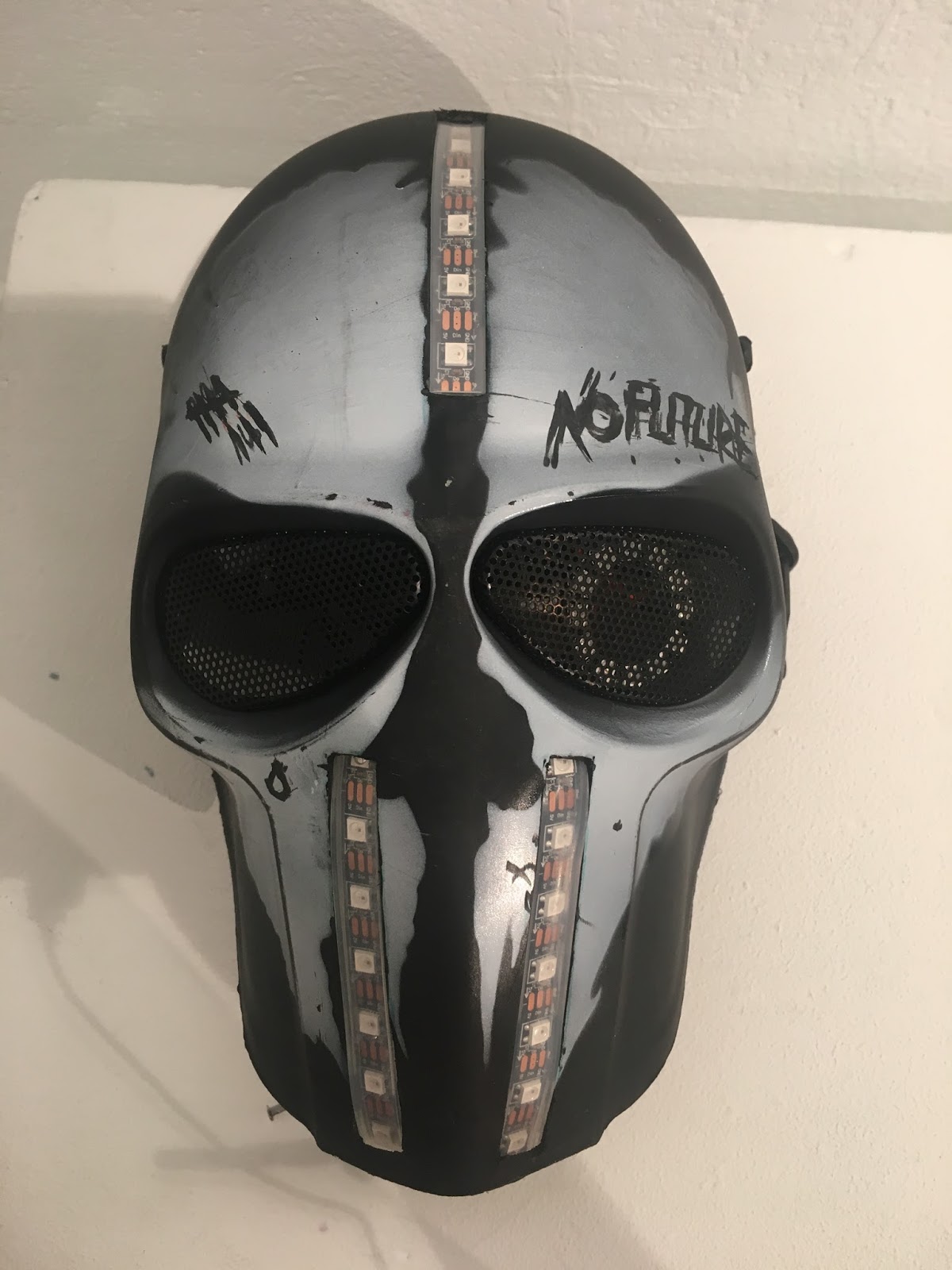
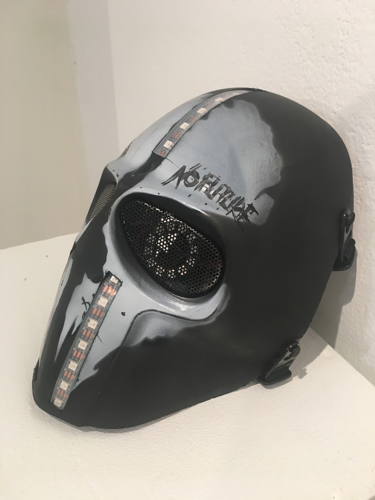
– For the Mask itself, I was more focused on where the LED strips were going to go than the wiring because there’s definitely no reversing saw after making a cut, and I have to carefully measure and plan where everything was going to go.
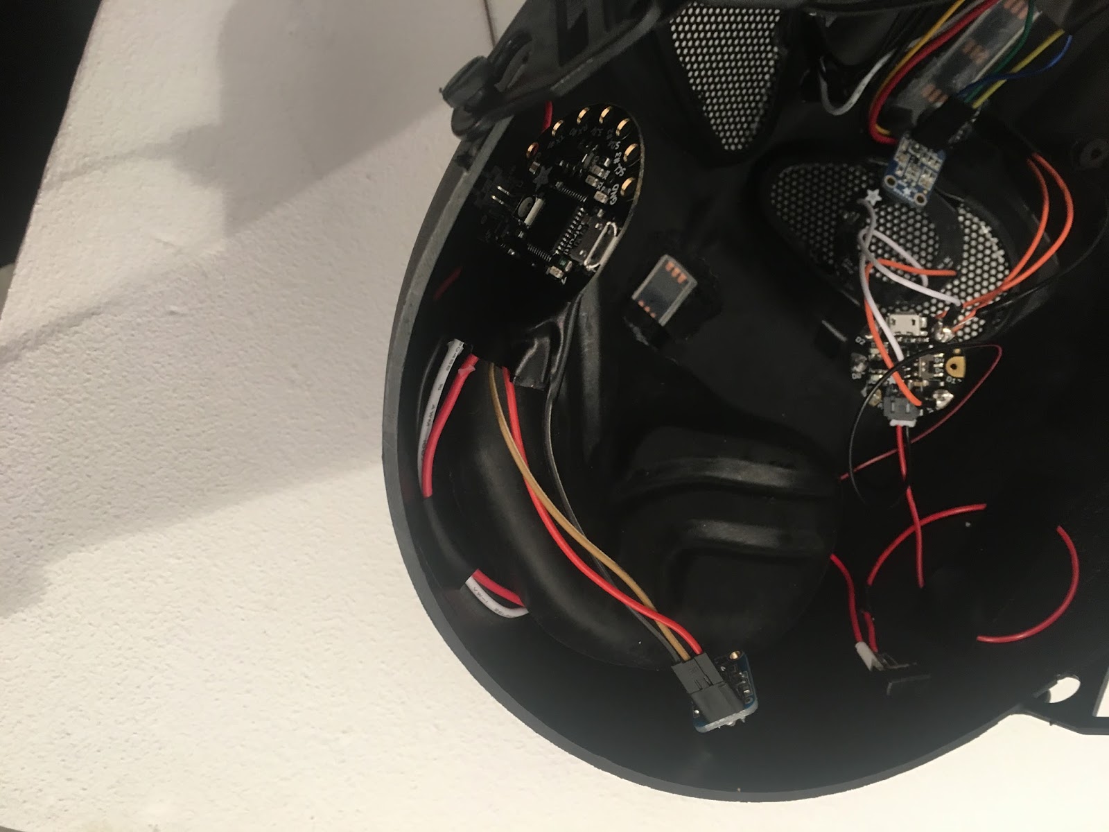
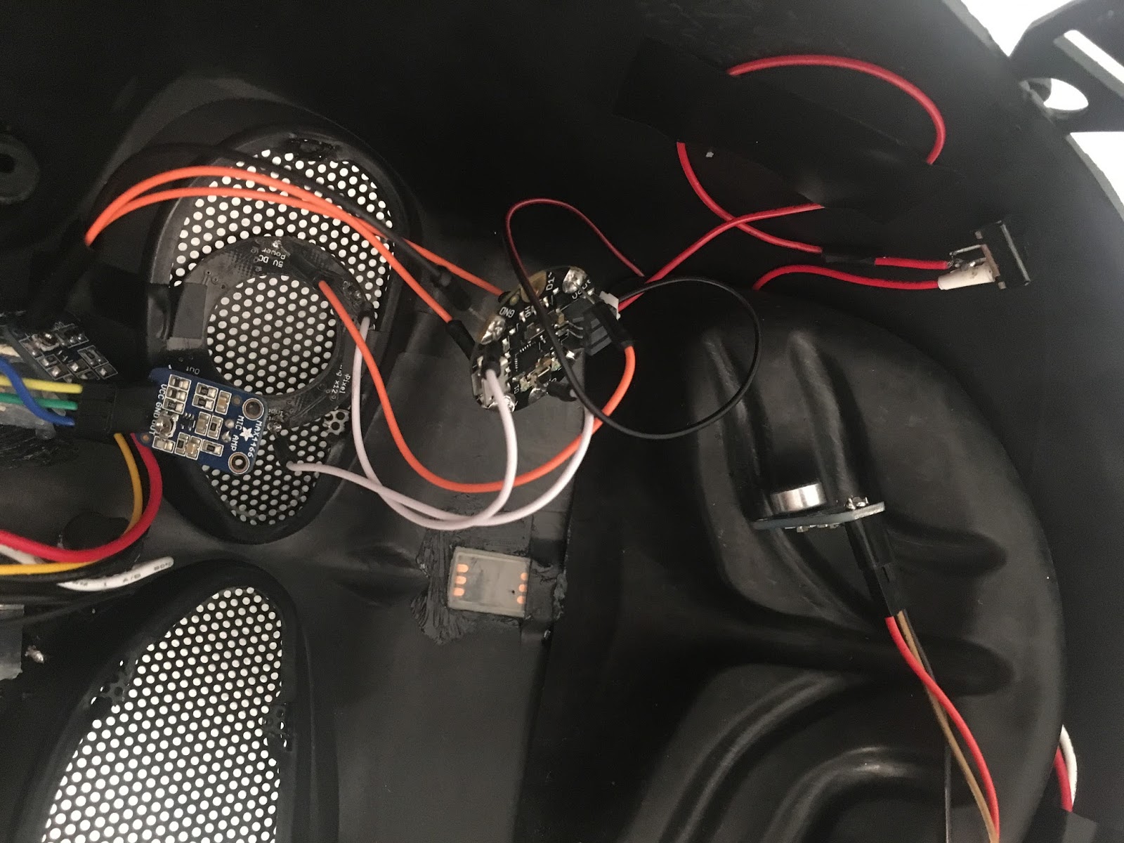
– The wires were not a problem because they are not going to be seen, even though the eyes; when they did, I taped them to the side of the mask or stuffed them under the padding.
– One switch and battery wasn’t going to be able to work for all three programmers, so I decided to give them all their own battery and I gave the smallest (GEMMA) the switch, while I just used the switch that was already on the programmers for the large ones.


