
A Wearable Song Count-in Device by Dustin Drenk
List of Materials for Build
- One hollow athletic wristband
- One hollow athletic headband
- Soldering Iron/Electronics Solder
- Stable Soldering Clamp
- Hot Glue Gun
- Multimeter
- Two dual 3V Watch Battery Enclosures; 6V Each for a total of 12V
- Four CR2032 3V Watch Batteries
- Electrical Tape
- Two Feet of Insulated Copper Wire; I pulled two from a ribbon cable TIP: Use Two Different Colors for so + and – connections do not get mixed!
- Copper Tape
- Thin Packaging Foam
- One Section of a 12V LED Strip that turns on only after it receives 12V
- Scissors
Step 1: Put the Four 3V Watch Batteries in the Two 6V Battery Enclosures
TIP: Use 6V Battery Enclosures that have an on/off switch so when the project is finished, the batteries can be turned off in case the pressure switch is accidentally engaged during transport eliminating accidental loss of battery power!
Step 2: Assemble Battery Enclosures

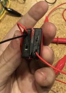

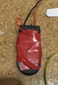
- Put the Copper Tape on the back of the Battery Enclosures; Cut the Copper Tape w/Scissors to Fill the backs of both Battery Enclosures
- Solder the two Battery Enclosures in A Series Configuration:
- Solder the + Wire (RED WIRE) from One Battery Enclosure to the Copper Tape on its back
- Solder the – Wire (BLACK WIRE) from the Other Battery Enclosure to the Copper Tape on its back
- Check the Connection using the Multimeter Set to Volts; By touching the Copper Tape on the back of each Battery Enclosure the Multimeter should read around 12.75V and 0V when not touching
- Cut out 2 Pieces of thin packaging foam that are the same size as the Copper Tape; Carefully fold foam pieces in half and cut out small slits in foam from each piece of foam
- Place the 2 pieces of foam on top the copper tape from one of the battery enclosures
- Cut 4-5 inches of electrical tape to secure the battery enclosures together; Keep this to the side
- TRICKY PART: Put the two backs of the battery enclosures together with the foam in the middle, with the Multimeter attached to the loose + and – wires and start applying pressure until the foam is situated in place so that when pressure is applied the Multimeter registers 12V and when no pressure is applied it registers 0V
- Carefully use pre-cut electrical tape to bind the loose soldered wires from each battery enclosure and also bind the two battery enclosures together without causing too much pressure, triggering the circuit.
Step 3: Prepare the Wristband to Accept Pressure Switch


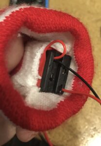
- Cut about an inch of the inner seam of the wristband
- Carefully Insert the Pressure Switch with the lead wires exiting out the cut hole
Step 4: Solder It Up! Phase 1
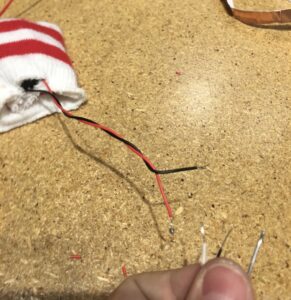

- Using the Stable Soldering Clamp solder the + and – wires from the Pressure Switch to stabilize them
- Solder the loose insulated copper cable; One to the + wire from the Pressure Switch and one to the – wire from the Pressure Switch
- Use Multimeter to test that the soldered connections are good
- Use the electrical tape first to separate the + and – wires then use it to reinforce the soldered connections and then use the Hot Glue Gun to double the reinforcement so that during movement the wires stay connected
- Use Multimeter to test that the soldered connections are good
Step 5: Solder It Up! Phase 2


TIP: The 12V LED Strip is very delicate and it is also hard to read the + and – terminals for soldering. DO NOT CLAMP THE 12V LED Strip to the Clamp Stand. THE TERMINALS ARE DELICATE!
- MAKE SURE YOU HAVE COLOR CODED THE + AND – WIRES BEFORE PROCEEDING
- Use the solder clamp to steady the free wires
- Prepare the + and – terminals on the 12V LED Strip by adding solder to wick each terminal
- Wick the wires and solder to the 12V LED Strip
- Activate the pressure switch to verify 12V LED Strip is properly connected in Series with the Pressure Switch
- Reinforce the solder junction with hot glue using the Hot Glue Gun
Step 6: Finishing Up!
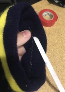


TIP: Threading the 12V LED Strip through the Headband can be tricky. Take your time with this and use the hollowness of the Headband to move the Strip forward, grab from outside, then pull. It is ok if the Strip is not fully in the Headband. This is because it will be pulled in when the Headband stretches to be worn either on the head or on the upper arm.
- Cut a small hole in the inner seam of the Headband
- Start threading the 12V LED Strip through the Headband. It is ok if the Strip doubles around inside the Headband (SEE TIP ABOVE)
- Test the build and adjust for size
- Have Fun Using it to Count In to a Song with your Band or use it to Communicate via Morse Code with a someone, but seriously, JUST HAVE FUN WITH IT!