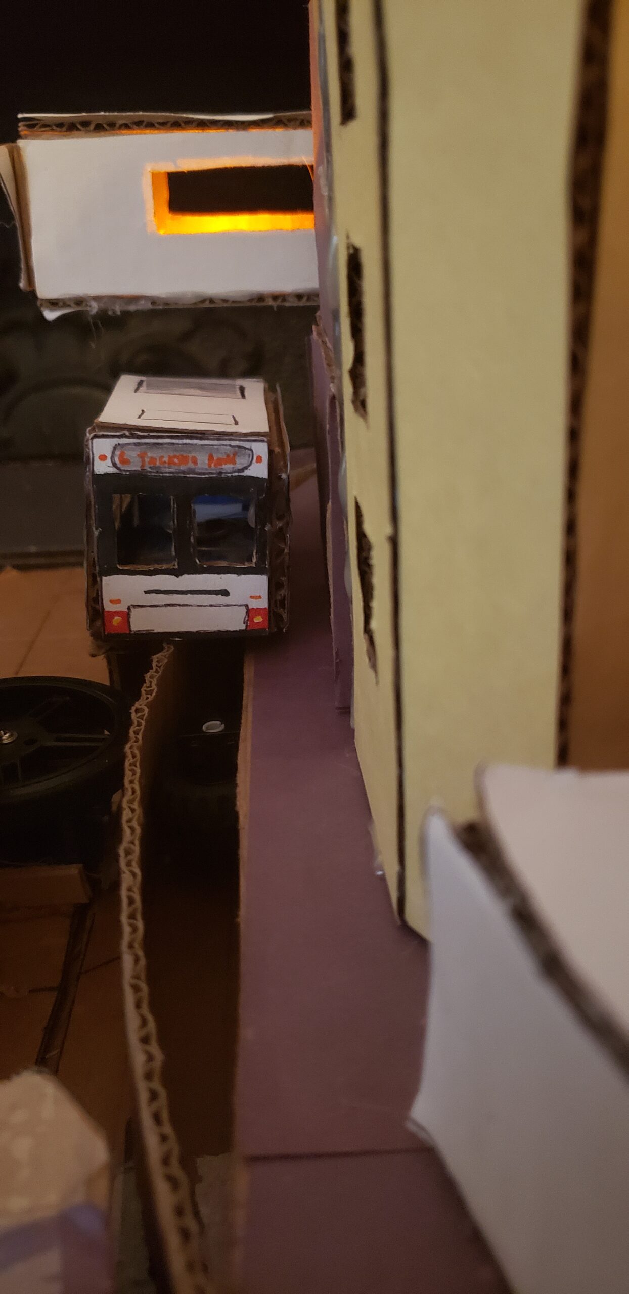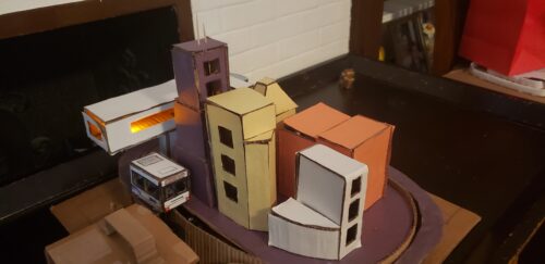
If you’ve ever been to the museum of Science and Industry then most likely you have come across their giant miniature scale model of Chicago that comes with working model trains that go from the city to the countryside. If you travel to the city frequently like myself then most likely you have taken public transportation whether that being a bus or a train. Well lets just say that these 2 things are the inspiration for this giant creation that I’m about to walk you through. What I have created is essentially a commuter ride that goes from my home to Chicago to my school and then back home. It’s my own version of that miniature scale model of Chicago from the museum but because i’m working with a smaller space, it’s essentially my commuter ride in a nutshell. The end goal is having your own miniature model of your commute to anywhere really, having a display to show off to your friends and family. It makes for a good decor piece. So hop on this bus and hold on to the railings as I take you through the many steps to build this model city and don’t worry, this ride is on me, okay let’s get going!
Materials: (Physical)
- Tons of cardboard (depending on your city, about 5 or 6 big sheets of it)
- Flash cards
- Boxing tape
- Hot glue gun (with sticks of glue to melt)
- Glue stick
- Box cutter and scissors
- Ruler
- Pencil/pen
- Markers (colors depend on your choice)
- 2 White LEDs
- Various colored LEDs
- Double sided conductive tape
- Adafruit circuit playground express
- Adafruit Crickit
- FS90R Continuous Servo + rubber wheel that comes with it
- Lwind 2 Light Mode 20 LED Cork Shape Wine Bottle Lights
- toothpicks
- 3 Lego wheels (the ones that are compatible with Technic pieces)
- Lego bricks
- data USB cable
- USB cable compabtable of connecting with the Adafruit crickit
- 1 Resister
- colored construction paper
- 3 3v coin cell batteries
Materials (Software)
- Arduino
Essentially this is like a giant puzzle except the image that you are trying to create is your own so for now let use mine, a commute ride from home to my school. To simplify this puzzle I’m going to break this into 5 giant parts: The Base, The Buildings, The Bus, The Mechanics, and the software. each piece will connect together and for that scale model of your commute ride.
Part 1: The Base, the mateirals you will need are:
- Cardboard
- hot glue
- Colored construction paper
To get started, you’re going to need a giant base, take a sheet of cardboard and cut out a square the size of: 18.5in. X 17.5in.
Next, you’re going to draw out an oval, this is the most important piece of the model as in this oval is where everything will happen. The dimensions of this oval will be along the lines of: 11in. X 18in. Of course you can make the oval bigger or even turn it into a giant circle, depending on how much space you want.
Next, With this oval drawn, take another sheet of cardboard and cut 2 ovals out of it with the exact measurements as the ovals that you drew.
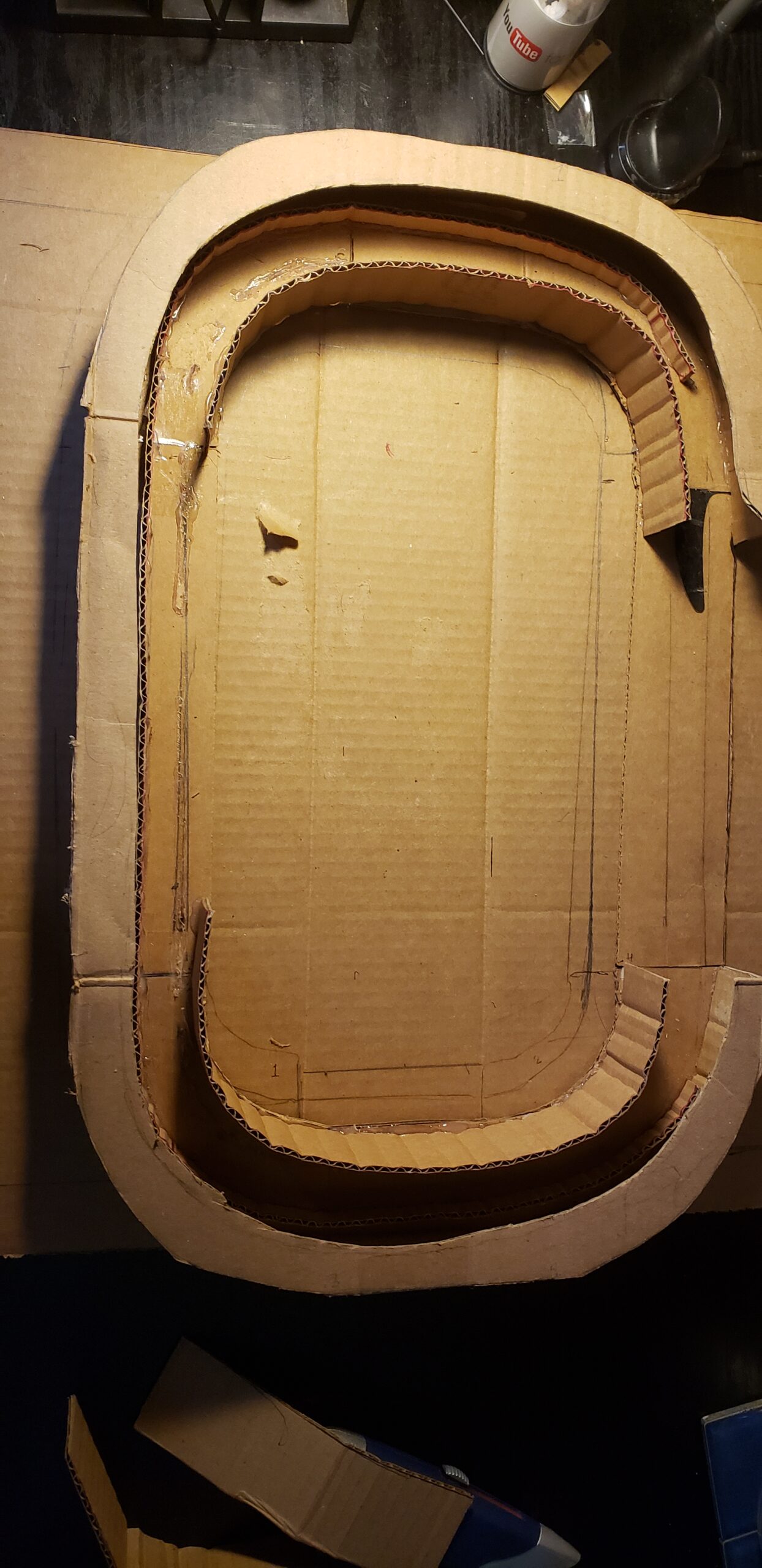
Now both of the ovals that you cut out, draw a line that goes 2 inches into the oval along 4 sides of it. Draw another oval that touches the end of those lines and now you have a smaller oval within the bigger one. You can leave it alone or you can cut the small oval out, which can help with alignment later on, in my piece I cut it out.
Next. taking one of the ovals, you’re going to cut out the smaller oval. Keep both the outer ring and small oval, we will use them again later.
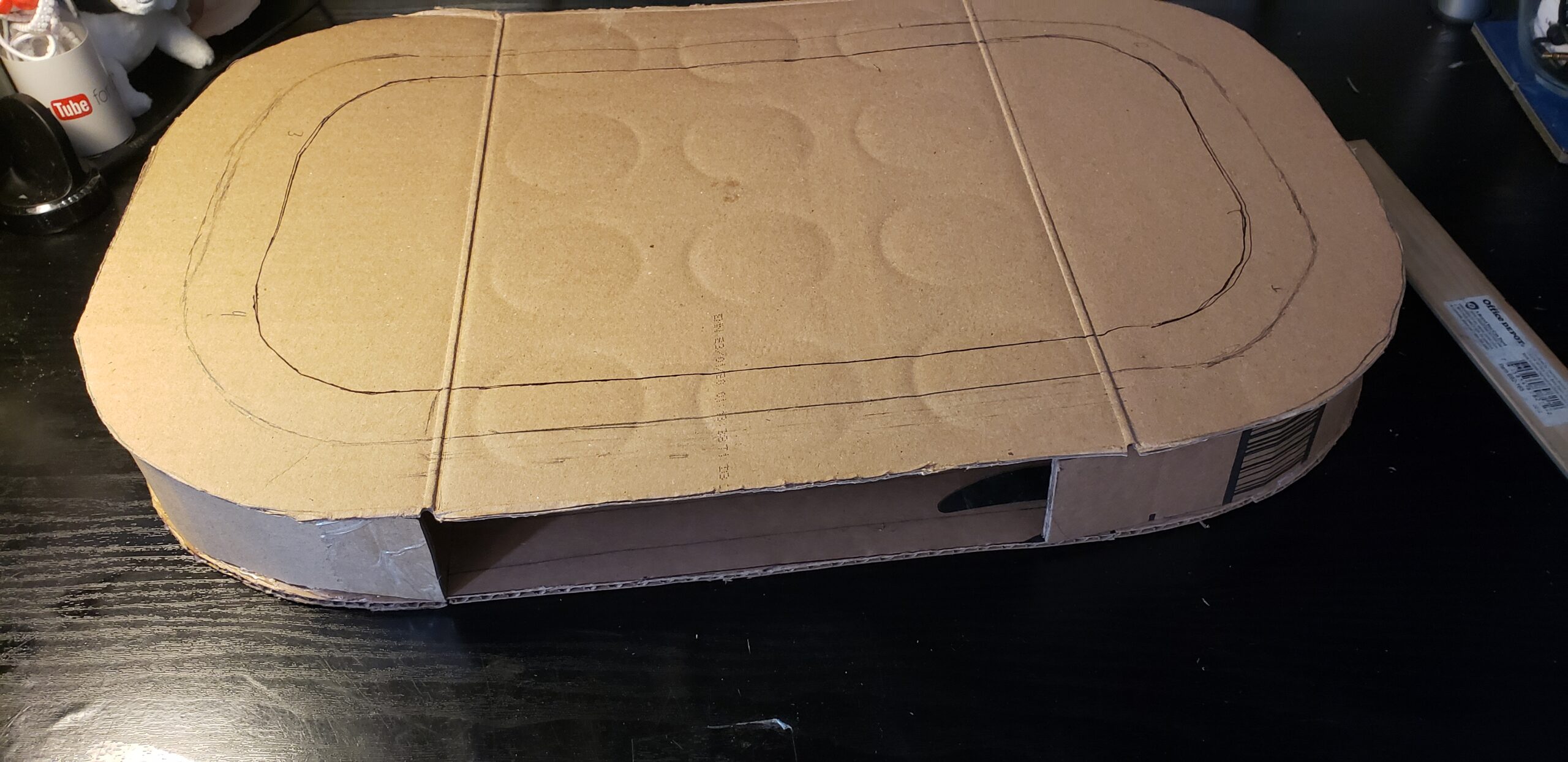
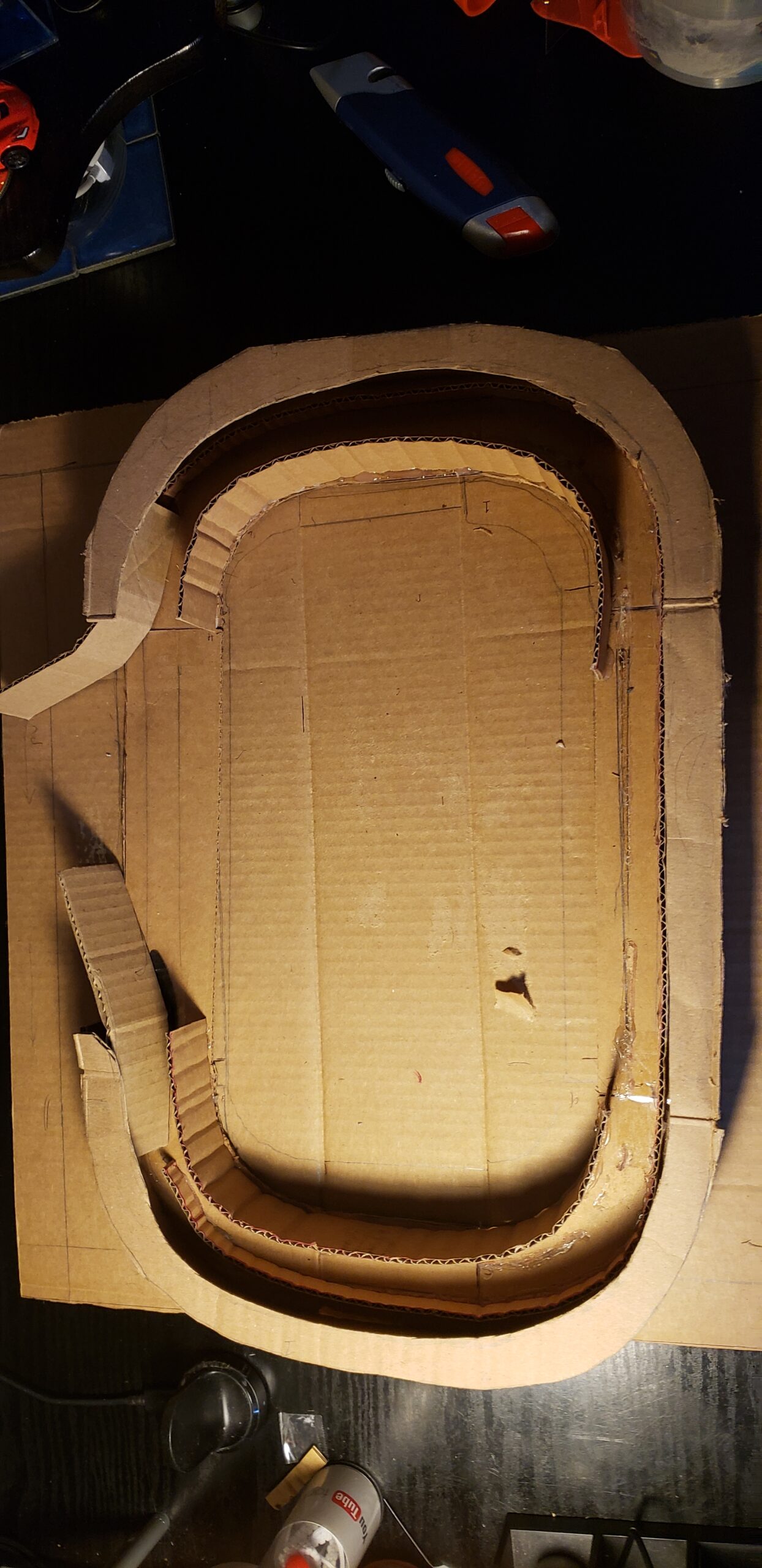
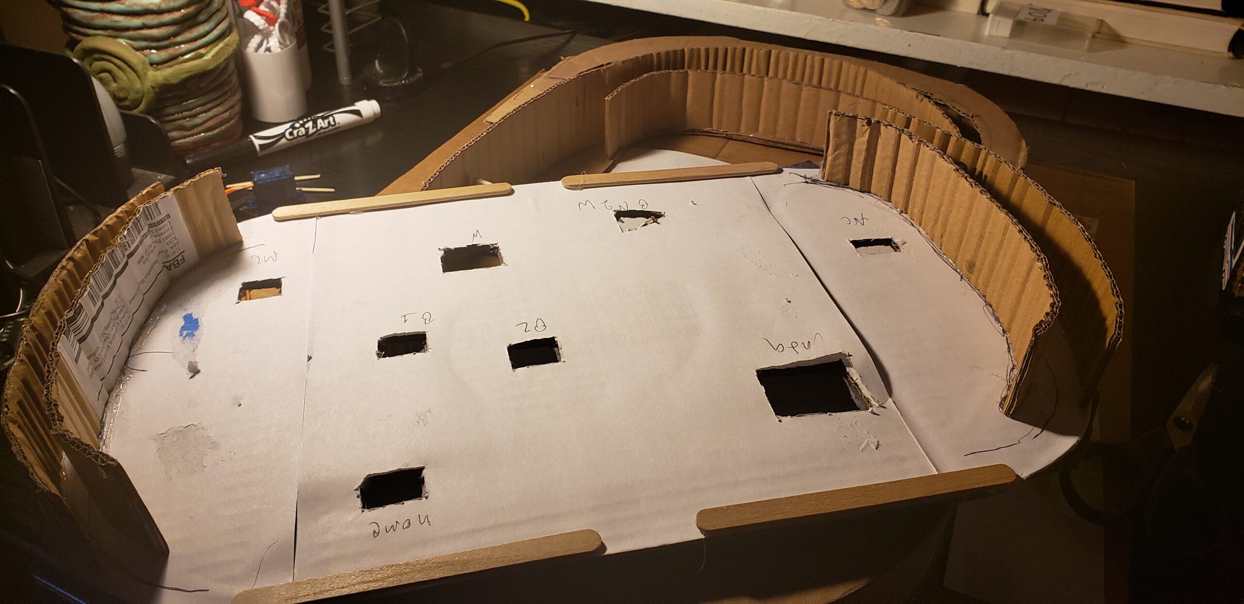
Next. we are going to cut out the walls for the piece, cut out 4 long strips of cardboard that measure ( 2in x 10in ), then start bending it from both front and back so it can easily curve to match the shape of the oval. Place 2 of them on the edge of the outside part of the oval on both sides (Note leave the long side of the oval open, the one that’s not a semi circle). hot glue the 2 onto the outside part. taking the other 2 strips lace them on the inside of the oval and hot glue them on, lining up with the ones glued on the outside.
Next, taking the outer ring that you cut earlier, place it on top of the 2 strips that are glued on the outside of the oval and glue onto the 2. taking the smaller oval, draw 1 inch into the oval on all sides and cut it, making the oval smaller. we will use this oval again in the Buildings step.
Next, the tread. This is what we will see moving around the oval. Take a long strip of cardboard, make sure that it is able to wrap around on the inside of the oval. if it’s not long enough, cut out some more strips and extend any shorter strips that you have. it should be 2in. in height. when your doing this, make sure the side with holes is exposed, this is crucial to put the bus on top of some of those holes.
Next, create a box with the measurements of:
- Side 1, 2, 3: 5in. x 3.5in.
- side 3 & 4: 5in. x 5in.
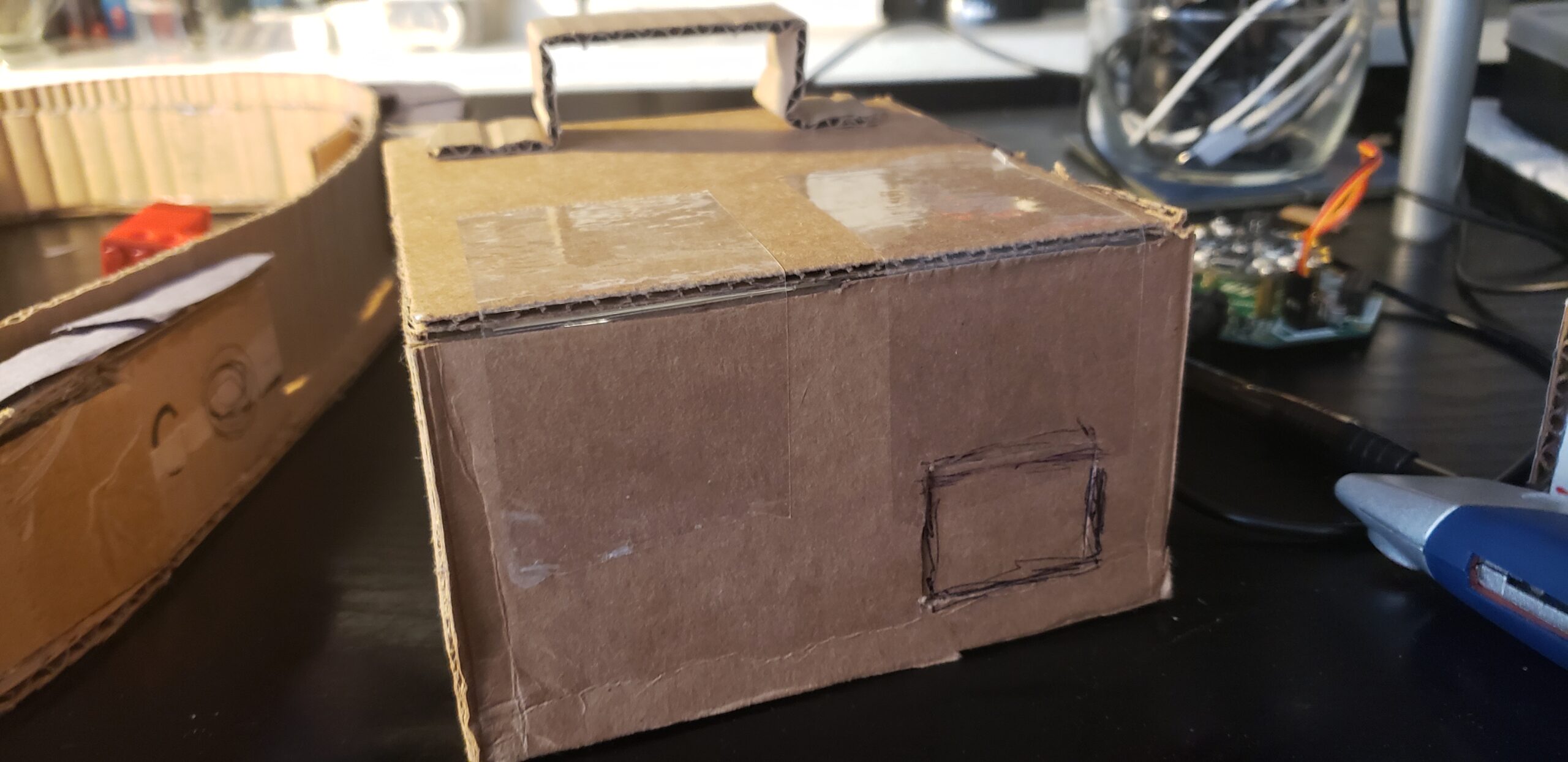
This is where we’ll house the Adafruit crickit and playground express. glue all sides together, notice how we are missing one side, this is where the the servo motor will interact with the tread. cut out a small hole (2 in. x 2 in.) in the right downside corner for the cables to pass through and into a power source. glue this box on one of the sides of the oval and we are done with part 1.
Part 2: The Buildings
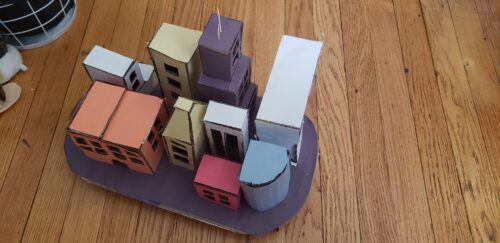
Perhaps this is the most personal preference based part of the piece, the buildings. These are the buildings that your mini bus/train will pass by so it’s up to you what kind of things that these buildings will pass by. The materials you will need for this part are:
- Lots of cardboard
- Tape
- Hot glue
- Lwind 2 Light Mode 20 LED Cork Shape Wine Bottle Lights
- 2 colored LEDs
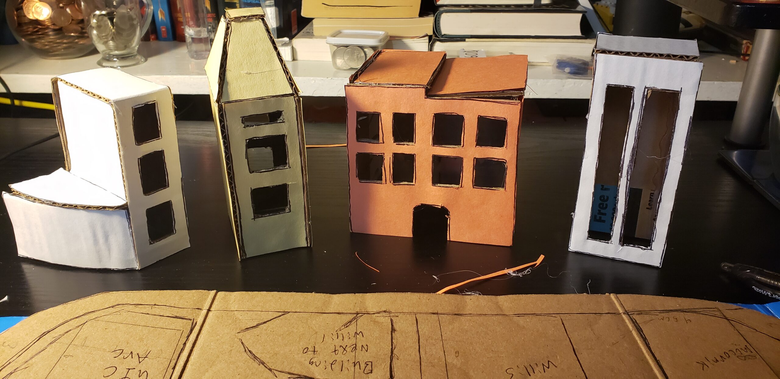
With my piece, since it’s my commute to school, the buildings are based on the ones that I pass by, each building has their own specific measurements.
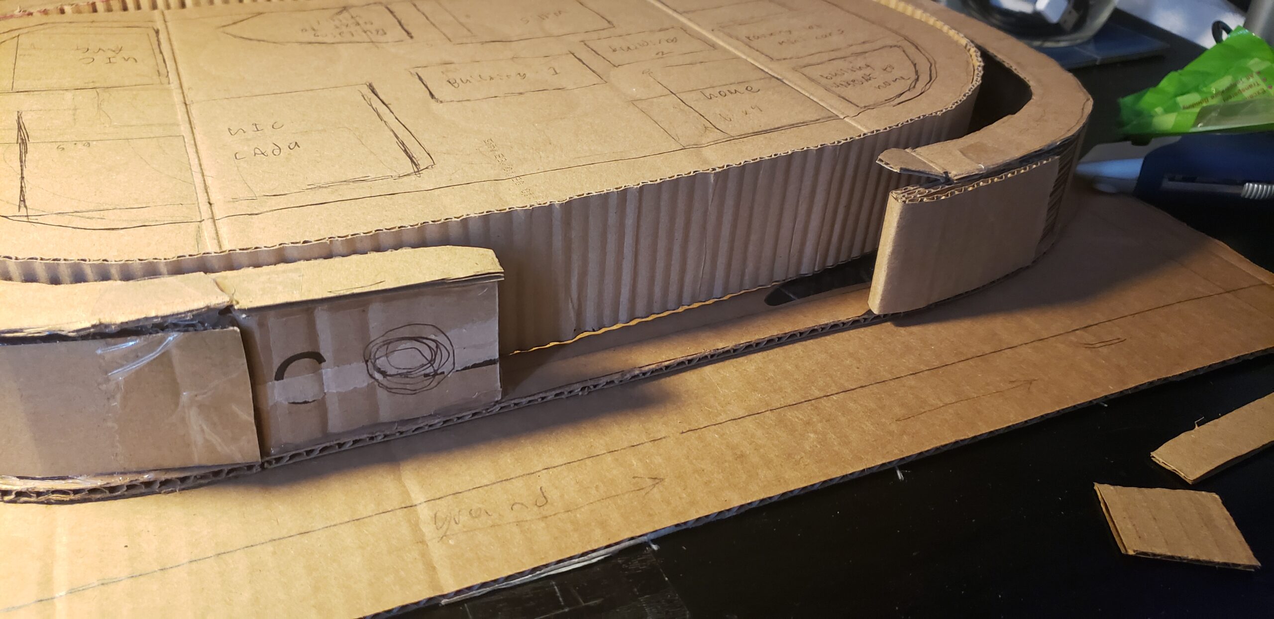
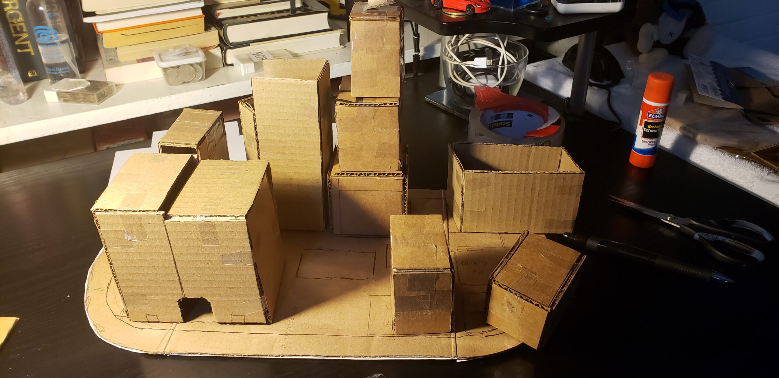
First, you want to draw the layout of where you will place the buildings and the measurements that go along with it
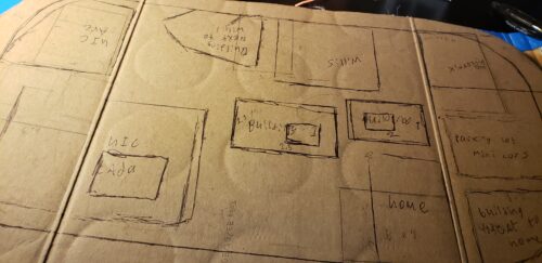
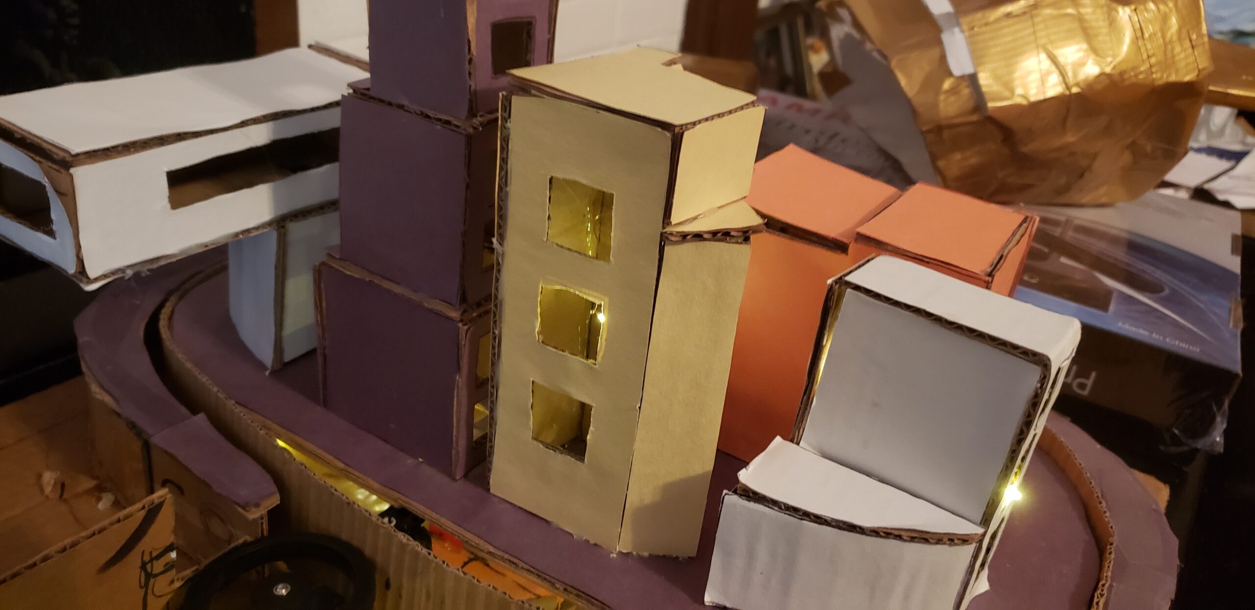
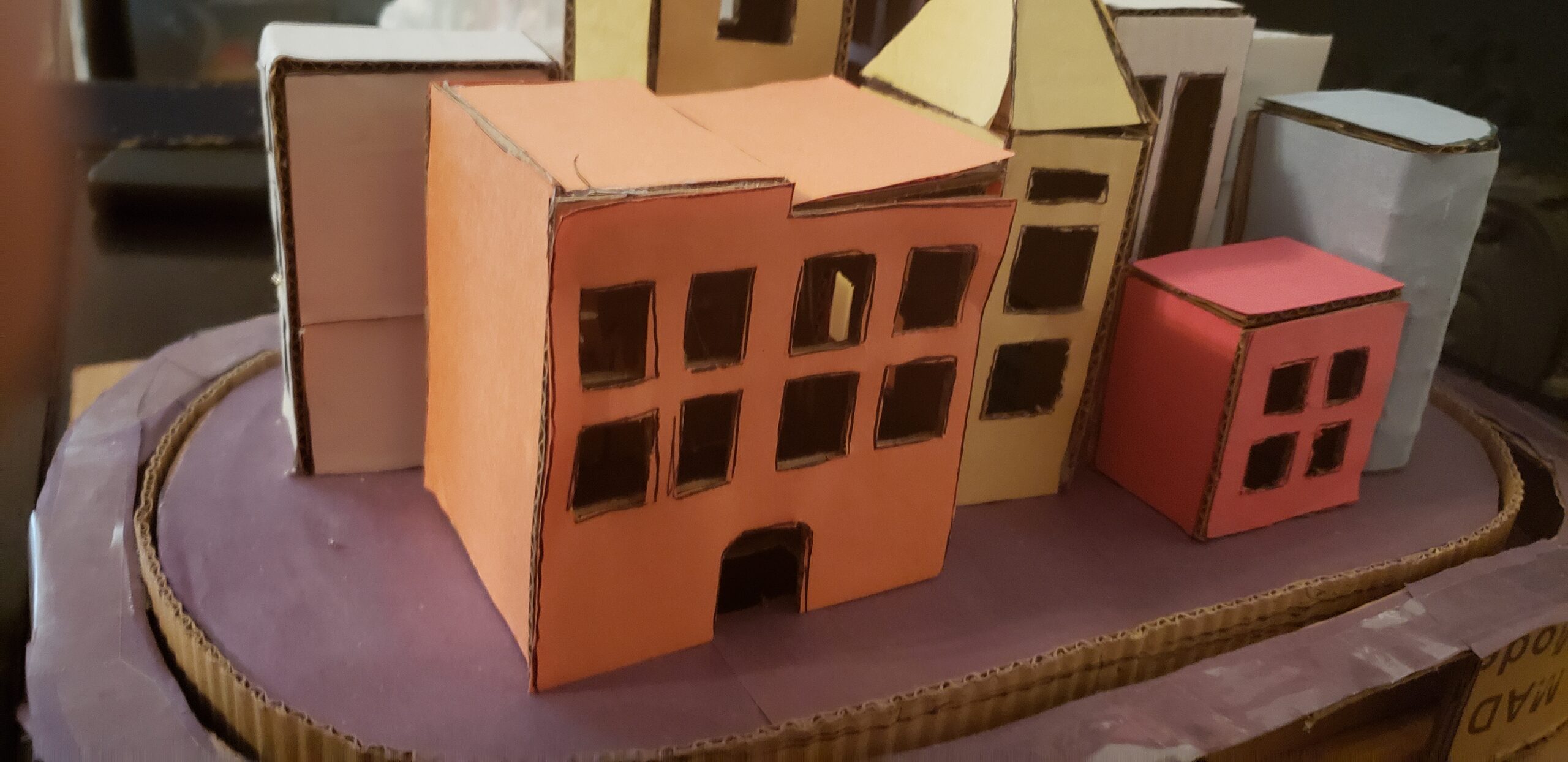
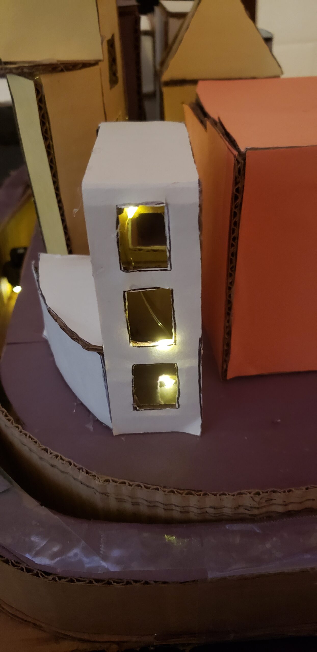
In total for my city there are 9 buildings, only 5 have lights in them, these buildings range from my home, the Willis tower, and buildings from UIC. The process for this part is simple: Cut, paint, and attach. Because the part is easier, I’ll just include some pictures and the measurements for some of the buildings, be sure to cut out some windows for the LEDs to shine through. (you can adjust measurements and add any other buildings if you want):
Building 1 (Home): 2.5in x 2in (x5)
Building 2 (the Willis Tower) 6in x 6 in (x5), 5in x 6in (x5), 4in x 6 in (x 5)
Building 3 (UIC Arc) 2in x 4 in (x 1), 4in x 4in (x2), 2in x 2in (x1), 2in x 6in (x1), 2in x 5in (x1)
Building 4 (UIC Cada Building) 8in x 7in (x2), 6in x 7in (x2), 8in x 6in (x1)
Building 5 (building in city 1) 4in x 8in (x2), 2in x 8 in (x2), 2in x 4in (x1)
Take the oval base that we saved, cover it with black construction paper, this is where the buildings will sit on. mark where you want the buildings. then, cut out small holes in the spots where you are going to hot glue the buildings on, this is for the LED light strips to slide on through.
After all are cut out, painted, and attached, they can now make their way onto the oval base, just hot glue them on and you’re all set.
Part 3: The bus.
Perhaps the most fun part of the process is creating the bus that will go around the city. The materials you will need for this step are:
- 1 sheet of cardboard
- 2 White LEDs
- 1 3v Coin cell battery
- Double sided conductive tape
- Flash cards
- Hot glue gun
- Markers (colors depend on your choice)
- Tape
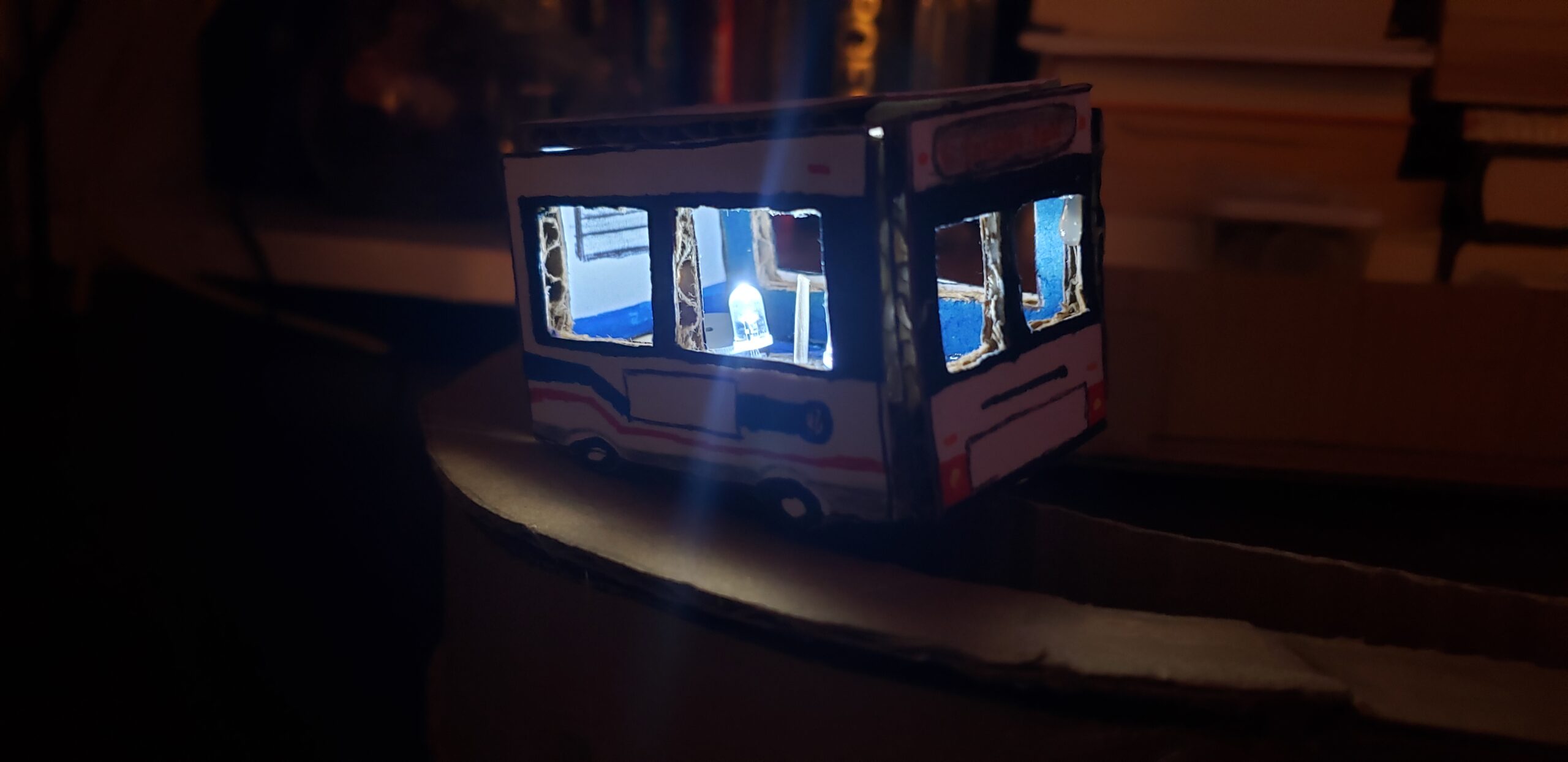
This part is mostly personal preference, you can create a bus or train from the place where you live. For this piece we’re making a CTA Bus from Chicago.
First, you’re going to take the sheet of cardboard and you’re going to cut out 6 pieces. Measurements include:
2 pieces that are 2.5in X 1.5in.
2 pieces that are 2.5in X 1.5in. The difference is that these will have 2 semi circles on the bottom to resemble wheels
2 pieces that are 1.5in X 1.5in
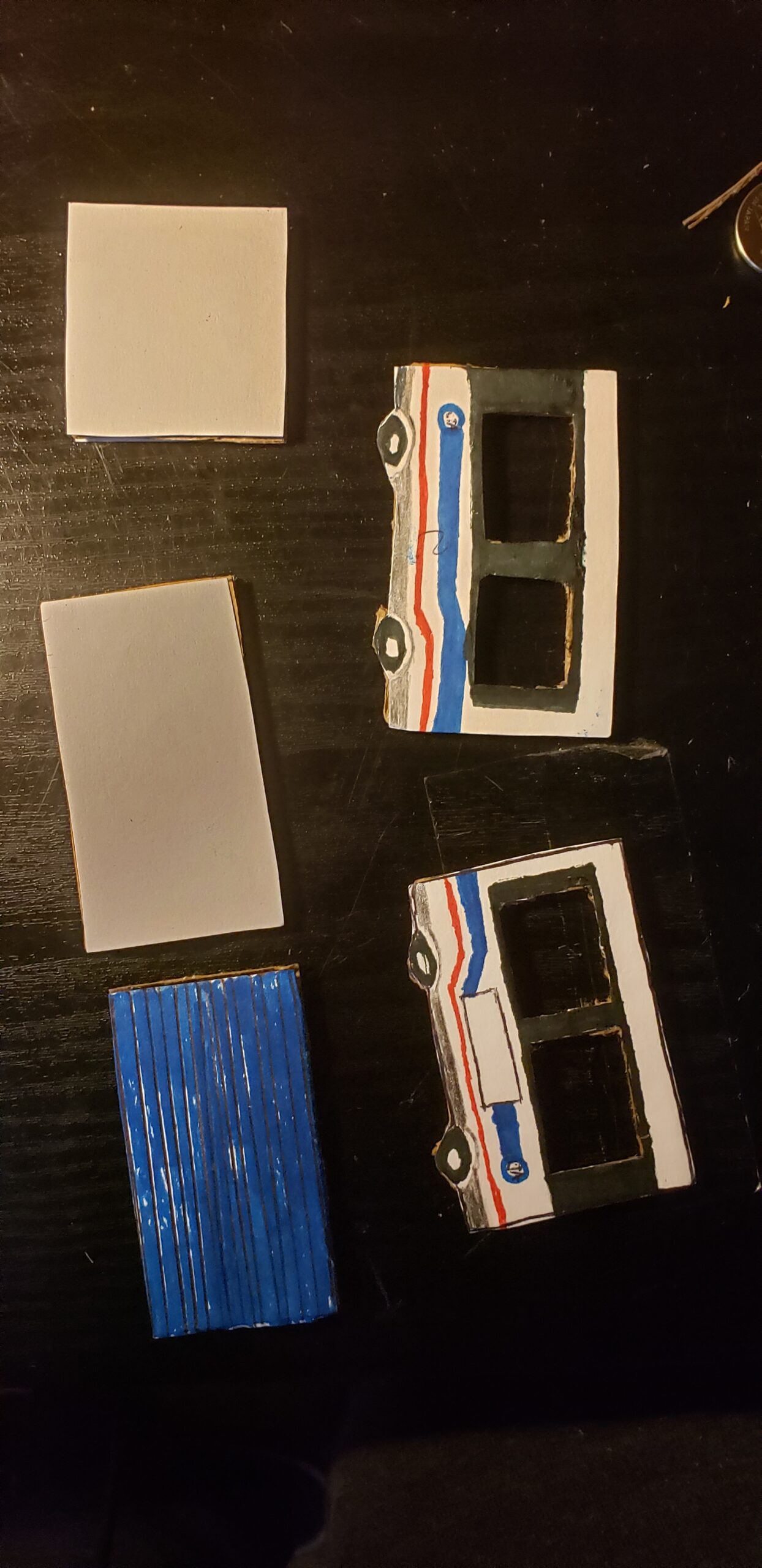
Next, take some flashcards and cut out shapes matching the cardboard cutouts, then glue the flashcard shapes onto the cardboard.
Next, using markers, fill in the blank flashcards with the design of a bus or train, (of course, you’re free to color it however you want).
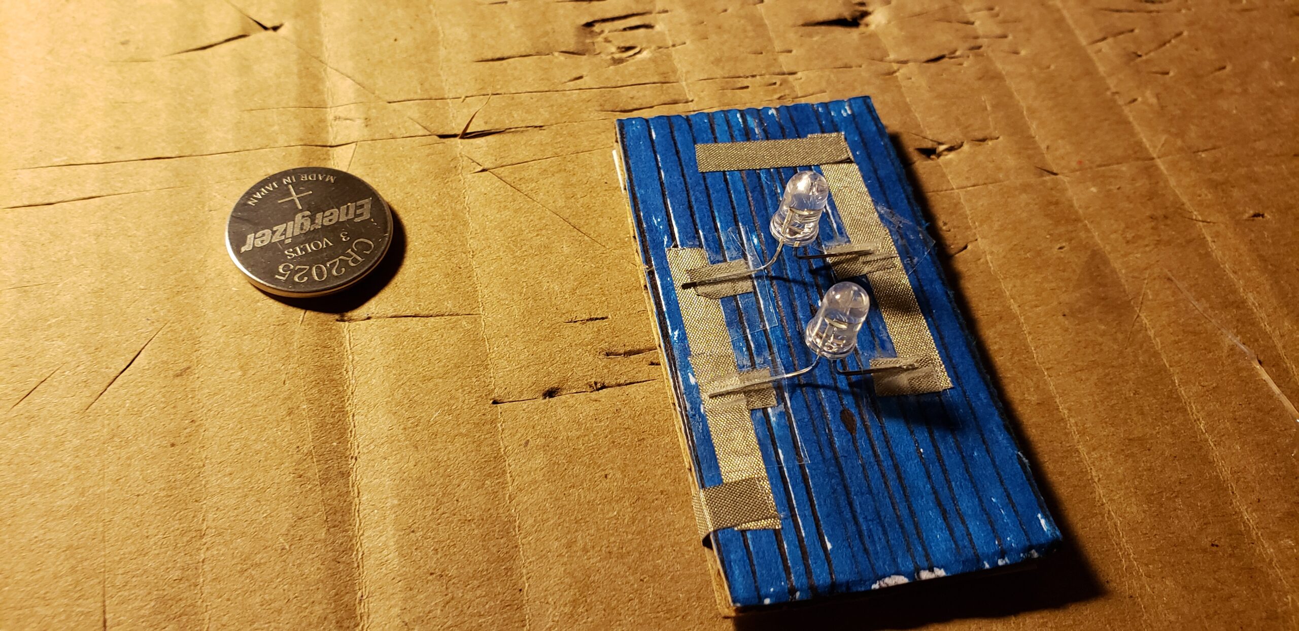
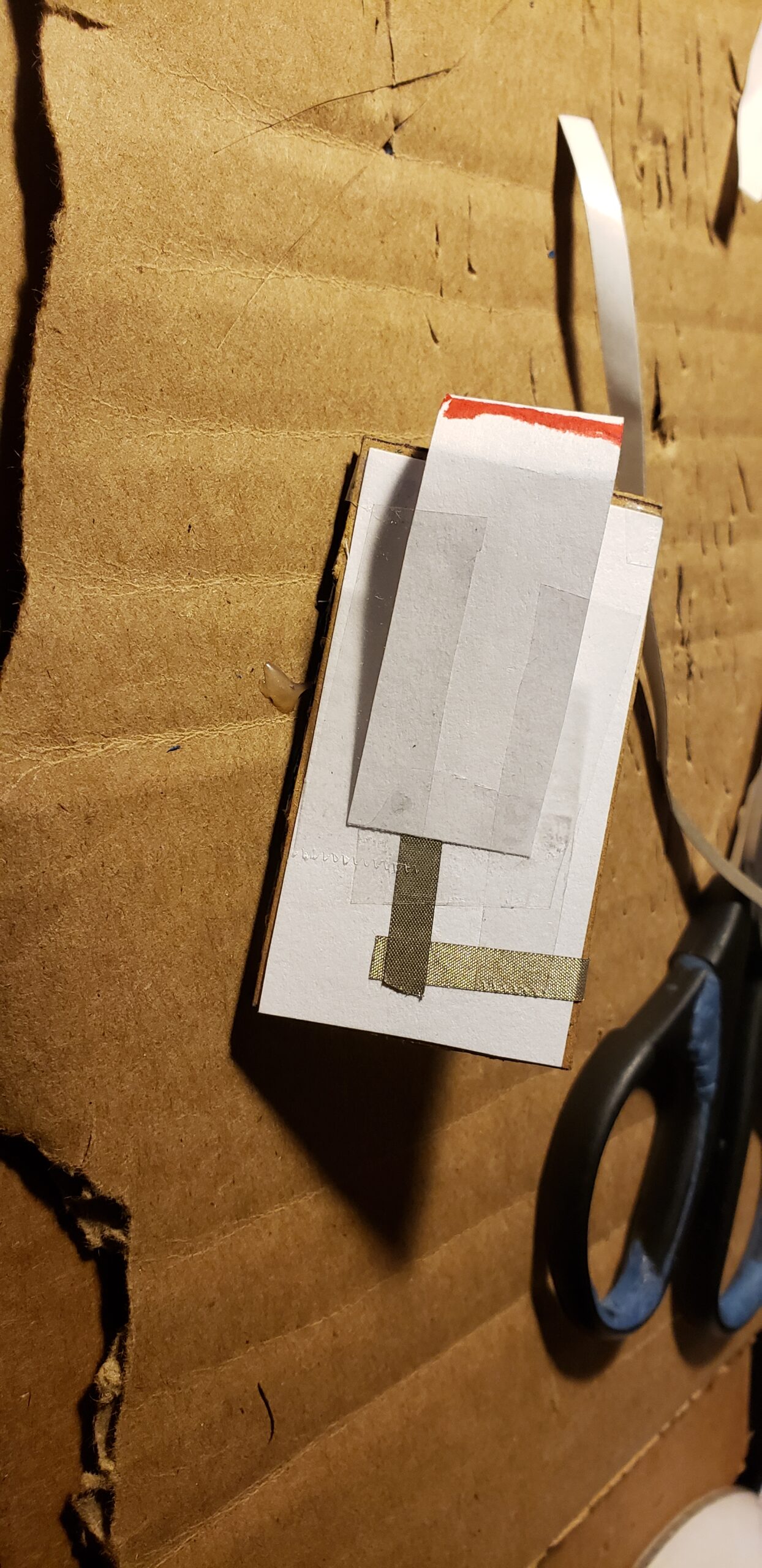
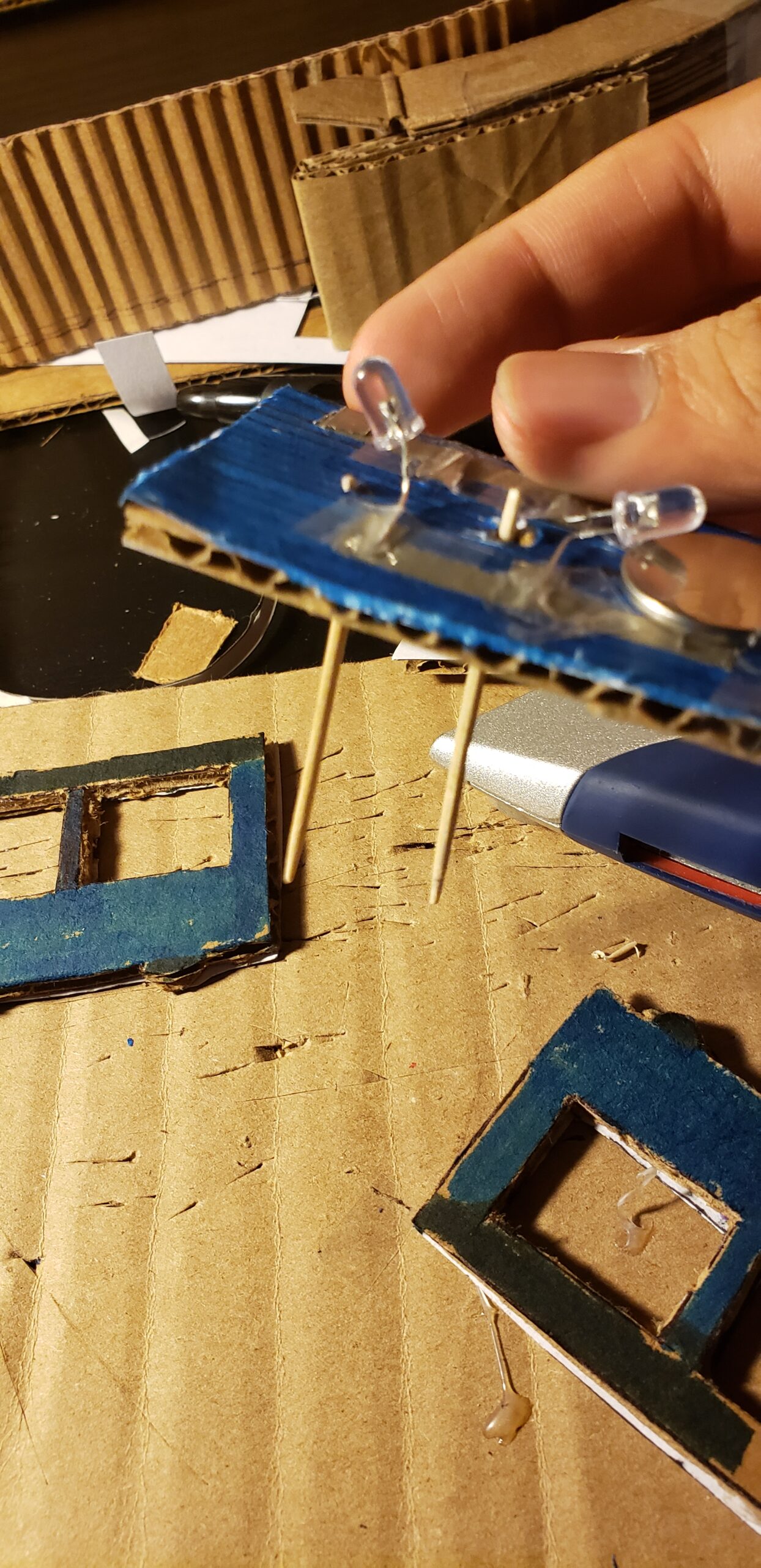
Next, take the piece that would go on the bottom of the bus, take some conductive tape and make a parallel circuit, (as seen in picture). The Coin cell battery gets attached to the back using a thin strip of tape. Place the 2 LEDs in their corresponding spot within the conductive tape. Tape the legs of the leds down so it sticks. Towards the front, the conductive tape goes over and under the piece of cardboard.
Next, Using the piece of cardboard that would be the back side of the bus, cut a tiny slit, 1 centimeter above from the edge of 1 side (as seen in picture).
Next, Cut a strip out from a flashcard and attach a strip of conductive tape onto it, (it should be as long as the strip of flashcard is). Now line up the strip of flashcard with the conductive tape to the conductive tape that’s on the cardboard that’s the bottom of the bus. Now slide the strip of flashcard through the slit and it should be able to touch the battery, thus completing the circuit and turning on the 2 LED lights, just pull out the slit to turn it off.
Next. Poke 2 holes in the bottom piece of the bus without cutting the conductive tape, this will be how it attaches to the tread within the base, making it move around the city.
Finally, Hot glue all the sides of the bus together. (Optional: don’t hot glue the roof, just tape it on, in a hinge type way, this enables you to be able to get inside the bus and adjust the battery and LEDs). In the end, you have a bus with lights that you can manually turn on, fun right?
Part 4: the Mechanics.
Probably the most difficult aspect of the piece is the mechanics as you kind of need some practice to get the components to work. I’ll split this part into 3 sub-parts: The Lego’s, the Servo and the Lights
The Lego’s:
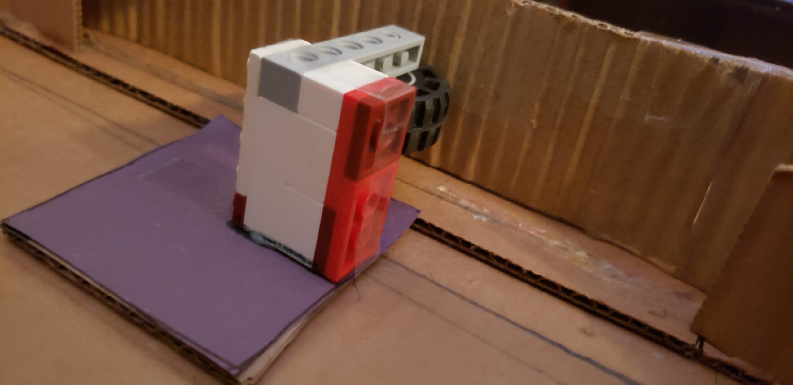
Using Technic pieces compatible with the Lego wheels plug them in, then gather some legos which include:
- 2×4 flat brick (x3)
- 1×2 flat brick (x3)
- 2×4 brick (x4)
- 2×2 brick (x6)
- 2×3 flat brick (x6)
- 2×2 flat brick (x6)
- 1×2 brick (x3)
- 1×6 technic brick with holes on the side (x3)
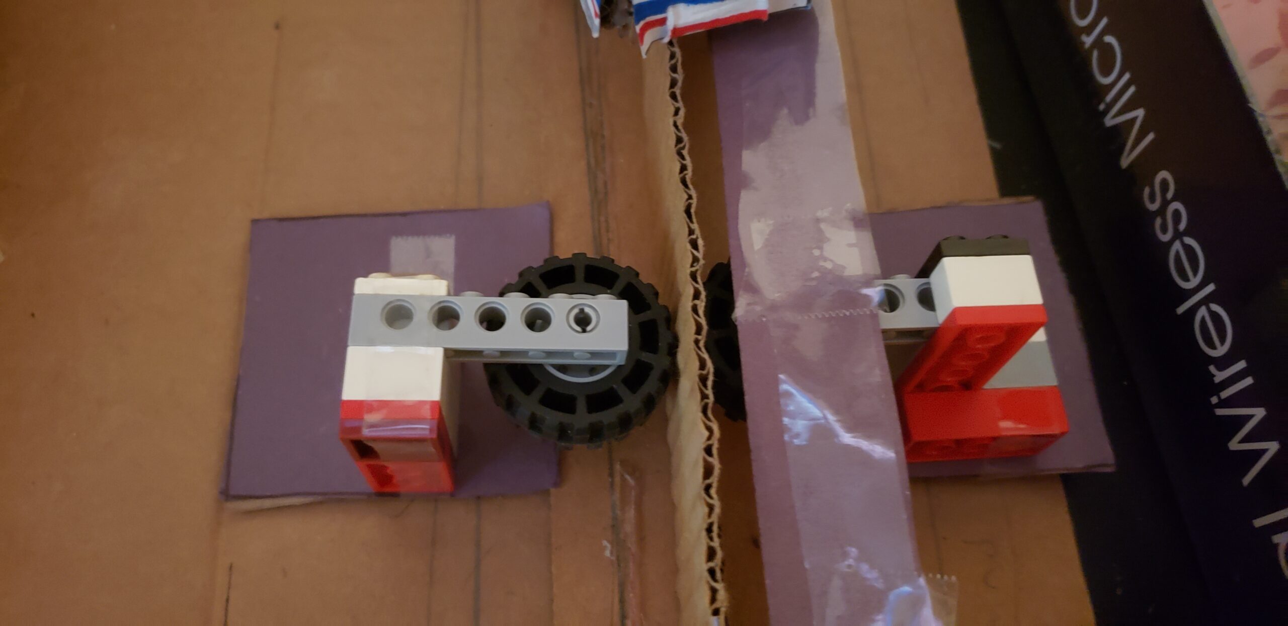
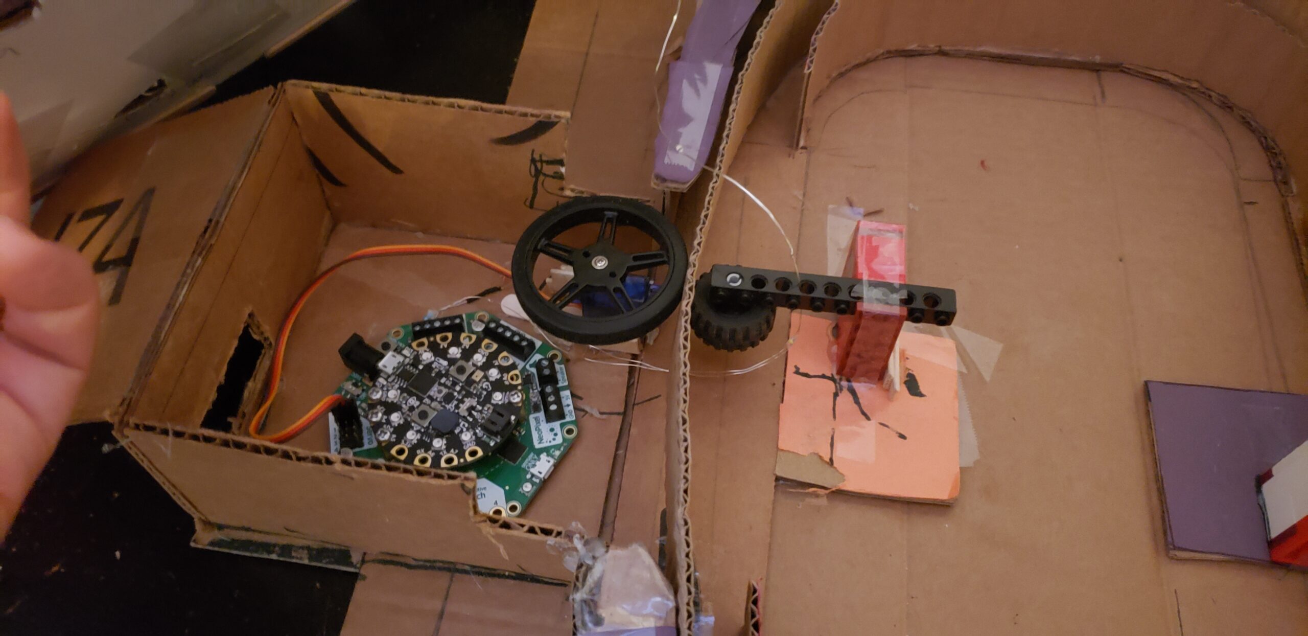
Next, put them together like the picture shows. make 2 of these and plug the Lego wheel into the last hole of the brick with holes in it. using the cardboard tread, take both of the Lego creations and put one on each side of the tread. it is important to make sure that the wheels are touching the tread. this will help things move more smooth. hot glue the Lego creations onto the base and that’s it.
create another one of these Lego wheel holders, we’ll come back to this step in a bit.
The Servo:
Next, the continuous servo motor, attach the rubber wheel that comes with it, tighten it using one of the nails and hot glue it inside of the little box created to house the crickit and circuit playground express. when you hot glue it, make sure the wheel is touching the tread, now take the other Lego wheel holder that you made and put it on the other side of the tread, opposite of where the continuous servo wheel is at. now you the tread is in place and if you want, activate the servo using the code in part 5 to see if flows smoothly, adjust if needed.
The Lights:
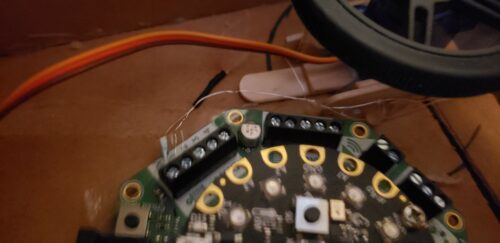
Taking the strip of LEDs, Slide them in the little holes that you cut under the base of where the buildings are at, I only used one but you can add more to fill up buildings with lights, make sure there’s enough to slide the connecting portion back into the crickit. plug it in as seen in the picuture and see if they turn on by using the code in part 5.
Part 5: The Software.
the materials required are: Adafruit Circuit playground express, Adafruit crickit, and 2 usb cables, one for receiving data and another to power the crickit.
for this project we are using Arduino, here is the code, simply plug in the boards using the USBs into your computer or laptop, boot up Arduino and copy and paste the code into it. Click “Check” to see if the code is fine and then you’re done.
Code:
#include <Adafruit_CircuitPlayground.h>
#include “Adafruit_Crickit.h”
#include “seesaw_servo.h”
Adafruit_Crickit crickit;
seesaw_Servo myservo(&crickit); // create servo object to control a servo
#include <FastLED.h>
#if defined(FASTLED_VERSION) && (FASTLED_VERSION < 3001000)
#warning “Requires FastLED 3.1 or later; check github for latest code.”
#endif
#define DATA_PIN A1
#define LED_TYPE WS2811
#define COLOR_ORDER GRB
#define NUM_LEDS 20 //10
CRGB leds[NUM_LEDS];
#define BRIGHTNESS 160 //96
// Variables:
int max_brightness = 65535; // absolute max brightness for string of LED’s
// the following variables are unsigned longs because the time, measured in
// milliseconds, will quickly become a bigger number than can be stored in an int.
unsigned long lastDebounceTime = 0; // the last time the output pin was toggled
unsigned long debounceDelay = 30; // the debounce time; increase if the output flickers
//_________________________________________________
void setup() {
Serial.begin(9600); //LED CODE
CircuitPlayground.begin(); // THIS LINE MUST BE BEFORE THE ‘crickit.begin()’,
// OR ELSE the Crickit signal (analog input) readings wont work!
if (!crickit.begin()) {
Serial.println(“ERROR!”);
while (1);
}
else Serial.println(“crickit started”);
// tell FastLED about the LED strip configuration
FastLED.addLeds<LED_TYPE, DATA_PIN, COLOR_ORDER>(leds, NUM_LEDS).setCorrection(TypicalLEDStrip);
// set master brightness control
FastLED.setBrightness(BRIGHTNESS);
Serial.begin(115200); //SERVO CODE
if(!crickit.begin()){
Serial.println(“ERROR!”);
while(1);
}
else Serial.println(“Crickit started”);
myservo.attach(CRICKIT_SERVO1); // attaches the servo to CRICKIT_SERVO1 pin
}
void loop() {
for (int p = 600; p < max_brightness; p = p + (random(30, 70))) {
crickit.analogWrite(CRICKIT_DRIVE1, p);
}
delay(random(50, 200));
for (int p = max_brightness; p >= 600; p = p – (random(20, 80))) {
crickit.analogWrite(CRICKIT_DRIVE1, p);
}
delay(random(60, 800));
myservo.write(90); //0
delay(90);
myservo.write(90); //90
delay(90);
//myservo.write(180); //180
//delay(6000);
// myservo.write(90); //90
// delay(1000); //delay is 1000
}
Finally: place everything together: First the base, then the base with the buildings, then place the tread, then place 2 toothpick within any of the holes of the tread, place the bus you made onto those toothpicks. place the Crickit and circuit playground in its box, plug in the power source, turn it on and watch the little bus go around. (Note; the tread tends to move up, you can fix it by tweaking the numbers for the servo in the code).
And there you have it, what I call Chicago in a nutshell, i hope if you build one of these for yourself that you take major creative liberties to personalize your own commuter experience!
