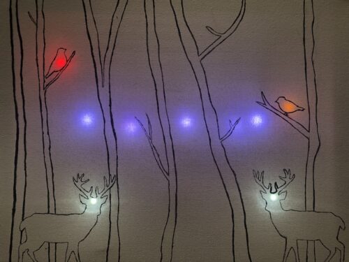
For my project, I made a sound reactive back-lit canvas. The lights behind the canvas turn on based on the loudness level of the sound the sound sensor on the Circuit Playground Express picks up.
Materials Needed:
- Your painted canvas
- A poster board (cardboard or any thin, sturdy material could work too)
- Soldering iron + solder
- Multicolored wire (for distinguishing purposes)
- 5 Neopixel strips with 10 neopixels on each
- 1 red LED, 1 yellow LED, and 2 white LEDS (or whatever colors you would like)
- 5 alligator clip with male ends
- 3 double sided alligator clip
- 1 wire nut
- Circuit Playground Express
STEP 1: Paint your canvas
You can leave it just as an outline and leave the painting for later if you’d like. Copy the sketch onto a poster board the size of your canvas. This will go behind the canvas and hold all the wiring; it will also serve as a guide as to where to place your LEDs and Neopixels strips.
STEP 2: Daisy-chain the neopixel strips
Get three different colors of wire, one for data, one for ground, and one for power. For ground and power, cut four 4-inch wires each and for data, cut four 9-inch wires. Strip both ends of all of them. I used purple for ground, yellow for power, and green for data.
![]()
Take one power wire and one ground and solder their respected pads (ground on GND, power on 5.5V, and data on DIN) on the back of the first neopixel strip. Take the other end of the wires and solder them on the front pads of the second strip. Take another power and ground wire pair and solder them to the back of the second strip. Repeat this for all the strips.
Take one data wire and solder it to the data out (DO) pad at the end of the first neopixel strip. Take the other end and solder it to the data in (DIN) pad of the second strip. Repeat this for the rest of the strips.
*Make sure the arrows for all the strips are pointing downwards.
TIP: Tape down the wires when soldering so they don’t move.
![]()
Arrange the neopixel strips between the trees drawn on the poster board as you’d like and tape the wires down.
![]()
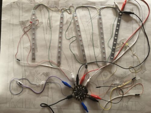
Take three alligator clips: one for ground, one for power, and one for data. Clip one end to the first neopixel strip and the other end to the Circuit Playground Express as follows: GND to GND, DIN to A1, and 5.5V to VOUT.
STEP 3: Wiring the LEDs
For each LED, cut and strip two wires of approximately 7 inches. Cut and strip an extra wire of approximately 4 inches. This will be the ground wire. Solder one end of the first wire to the male end of an alligator clip with a male end and the other end to the positive leg of the LED. Clip the alligator clip to an I/O pin on the Circuit Playground Express (I used pins A2, A3, A5, and A7). Solder one end of the second wire to the negative end of the LED. Gather the other end of the second wire for all the LEDs and one end of the ground wire and twist them together. Take a wire nut and screw it on the twisted wires.
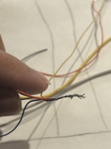
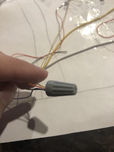
Take the other end of the ground wire and solder it to the male end of an alligator clip with a male end. Clip the alligator clip to a GND pin on the Circuit Playground Express. Tape all the wiring on to the poster.
Complete wiring:
STEP 4: Seal the canvas
Place the canvas on top of the poster board and hot glue the edges to wood frame, leaving an opening for the wire to come out.
STEP 5: Upload the code
Place your painted canvas on top of the poster board. Connect the Circuit Playground Express into your computer, upload the code, and watch your canvas come to life!
***************ARDUINO CODE***************
#include <Adafruit_CircuitPlayground.h>
#include <FastLED.h>
#define DATA_PIN A1
#define NUM_LEDS 50
CRGB leds[NUM_LEDS];
int analogPinAntelersRight = A5;
int analogPinAntelersLeft = A3;
int analogPinBirdsRight = A7;
int analogPinBirdsLeft = A2;
void setup() {
CircuitPlayground.begin();
Serial.begin(115200);
pinMode(analogPinAntelersRight, OUTPUT);
pinMode(analogPinAntelersLeft, OUTPUT);
pinMode(analogPinBirdsRight, OUTPUT);
pinMode(analogPinBirdsLeft, OUTPUT);
FastLED.addLeds<NEOPIXEL, DATA_PIN>(leds, NUM_LEDS);
FastLED.setBrightness(128); //half brightness
}
void loop() {
int soundLevel = CircuitPlayground.mic.soundPressureLevel(10); //sound level checked every .1 seconds
soundLevel = abs(soundLevel);
Serial.println(soundLevel);
Serial.write(soundLevel);
//Neopixels activated with sound
if(soundLevel > 57)
{
for(int i=0; i<10; i++){ //light falling down pattern
leds[i].setRGB(125, 125, 255); //first strip
leds[i+10].setRGB(125, 125, 255); //second strip
leds[i+20].setRGB(125, 125, 255); //third strip
leds[i+30].setRGB(125, 125, 255); //fourth strip
leds[i+40].setRGB(125, 125, 255); //fifth strip
FastLED.show();
delay(750);
leds[i] = CRGB::Black;
leds[i+10] = CRGB::Black;
leds[i+20] = CRGB::Black;
leds[i+30] = CRGB::Black;
leds[i+40] = CRGB::Black;
}
}
//The leds behind the two birds and the antelers of the deer will light up with sound
if(soundLevel > 85){
digitalWrite(analogPinBirdsRight, HIGH); //bird leds turn on
digitalWrite(analogPinBirdsLeft, HIGH); //bird leds turn on
digitalWrite(analogPinAntelersRight, HIGH); //anteler leds turn on
digitalWrite(analogPinAntelersLeft, HIGH); //anteler leds turn on
delay(10000); //leds are on for 10 seconds
}
if(soundLevel > 75){
digitalWrite(analogPinAntelersRight, HIGH); //anteler leds turn on
digitalWrite(analogPinAntelersLeft, HIGH); //anteler leds turn on
delay(10000); //leds are on for 10 seconds
}
else{
digitalWrite(analogPinAntelersRight, LOW); //anteler leds are off
digitalWrite(analogPinAntelersLeft, LOW); //anteler leds are off
digitalWrite(analogPinBirdsRight, LOW); //bird leds are off
digitalWrite(analogPinBirdsLeft, LOW); //bird leds are off
}
}
I also made a complementary processing sketch that shows the “other side” of the what’s happening in the painting. It places footprints in the snow as the Circuit Playground Express sound sensor picks up sound higher than a certain level.
***************PROCESSING CODE***************
import processing.serial.*;
Serial myPort;
int sound;
PImage forest;
PImage footprint;
void setup() {
size(1280, 1024);
forest = loadImage(“forest_background_cropped.png”);
image(forest, 0, 0);
printArray(Serial.list());
// String portName = Serial.list()[0];
myPort = new Serial(this, “COM5”, 9600);
}
void draw() {
footprint = loadImage(“footprints.png”);
while(myPort.available() > 0) {
sound = myPort.read();
}
println(sound);
if(sound > 75){
image(footprint, random(156, 800), random(765, 1000));
}
}
The images in the code:
